Supercharge Your Innovation With Domain-Expert AI Agents!

Wire feed mechanism

Active Publication Date: 2018-01-04
DAIHEN CORP
View PDF2 Cites 1 Cited by
  • Summary
  • Abstract
  • Description
  • Claims
  • Application Information

AI Technical Summary

Benefits of technology

The technical effect of this patent text is to provide a more efficient and cost-effective method for producing a specific type of material. This method involves a specific process involving a series of steps and ingredients that work together to create the desired material. This process is designed to yield higher quality material in a more efficient way.

Problems solved by technology

Unfavorably, such pressure handle configuration may be a factor that hinders a reduction in the size of the wire feeder.

Method used


Image

  • Wire feed mechanism
  • Wire feed mechanism
  • Wire feed mechanism

Examples


Embodiment Construction

[0024]Preferable embodiments of the present invention will be described below with reference to the drawings.

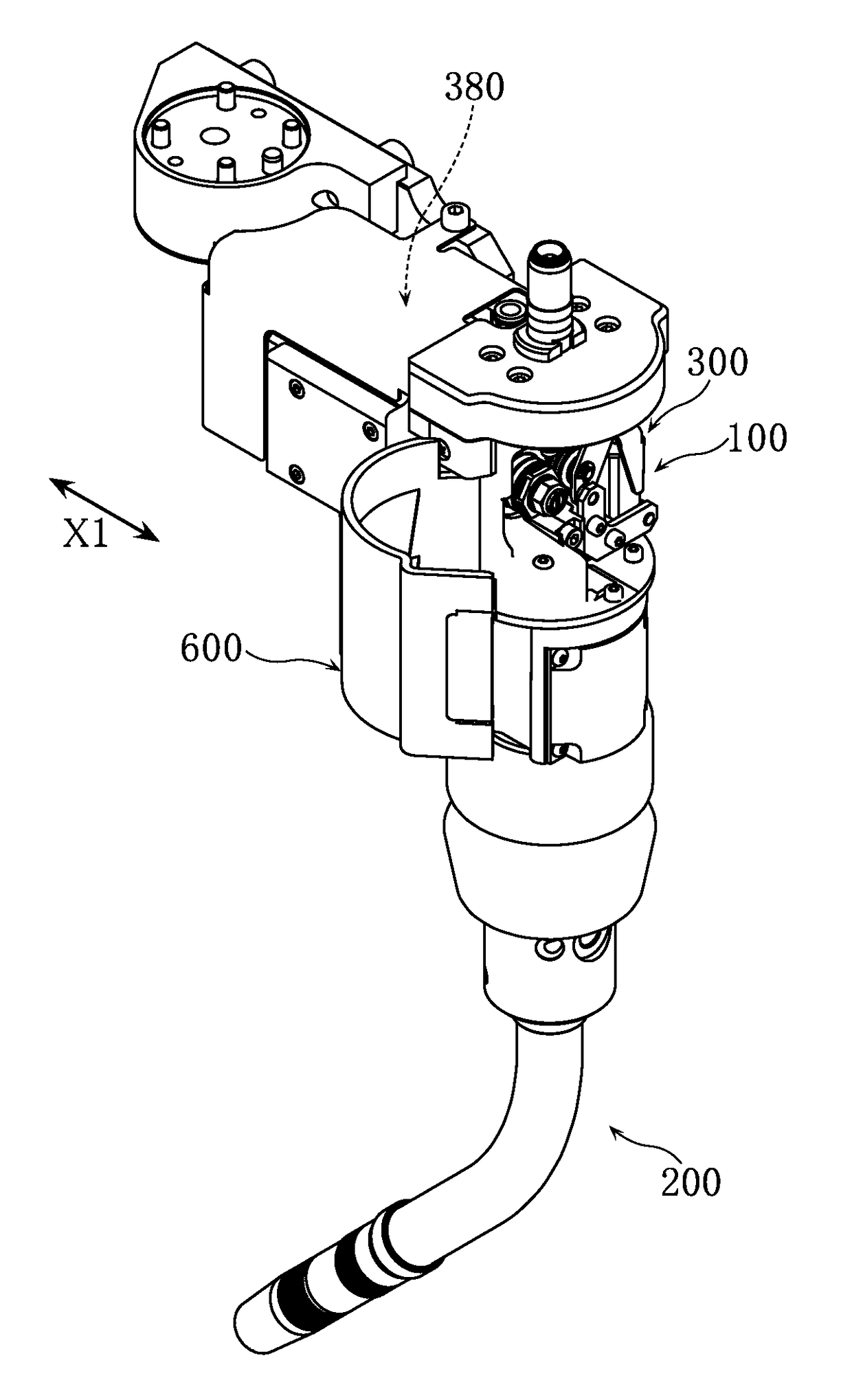
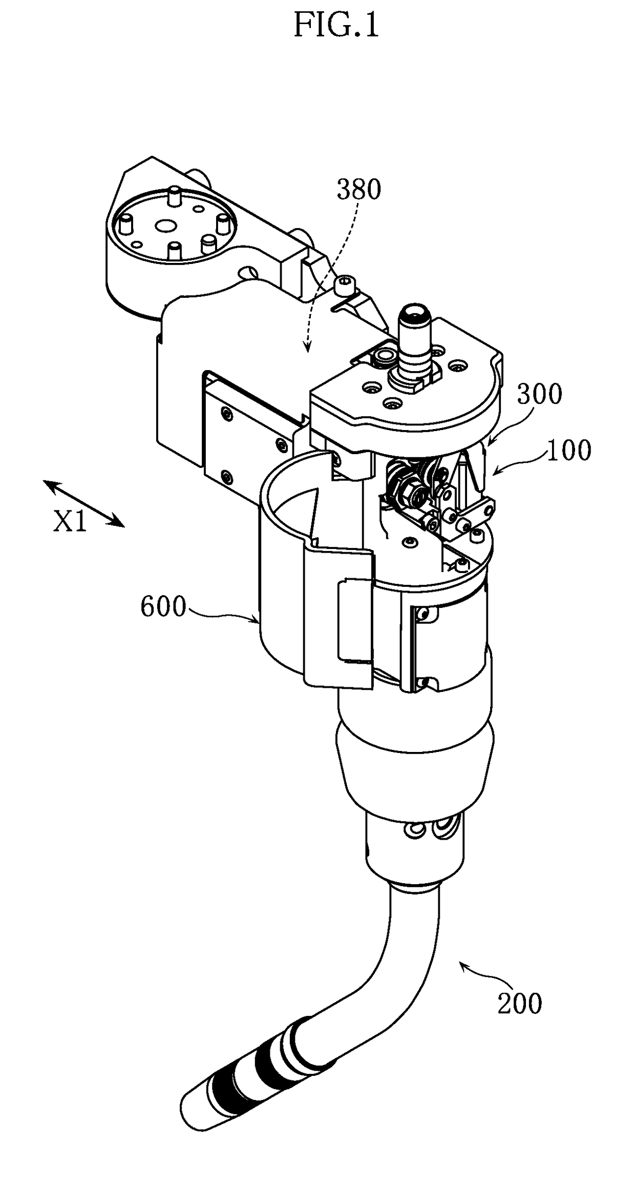
[0025]FIG. 1 is a perspective view showing a welding torch 200 that includes a feeder 100, in which a wire feed mechanism according to an embodiment is incorporated. FIG. 2 is an elevational view of the welding torch 200. For example, the welding torch 200 is attached to a wrist portion of a manipulator that is configured as a multi-joint robot constituted by a plurality of arms, and is used to perform automatic welding, such as consumable electrode gas shield arc welding. A welding wire (hereinafter referred to simply as a “wire”) is fed to the welding torch 200 via a given cable (e.g. a conduit cable or a power cable etc.). Specifically, a power supply chip is provided within the welding torch 200 on the leading end side thereof. The wire is fed within the welding torch 200 toward the power supply chip by the feeder 100, and is then sent to the outside from an opening at th...


PUM

PropertyMeasurementUnit
Forceaaaaaaaaaa
Distanceaaaaaaaaaa

Abstract

The wire feed mechanism includes a feed roll, a pressure roll, a pressure arm, and a pressure mechanism. The feed roll rotates around a rotation axis. The pressure roll is displaceable relative to the feed roll. The pressure arm has a first end and a second end that are separate from each other, and rotatably supports the pressure roll. The pressure mechanism engages with the pressure arm so that a pressure force is applied from the pressure roll to the feed roll with a wire held between the feed roll and the pressure roll. A force-receiving portion is provided at an end of the pressure arm. When the pressure roll presses the feed roll, the pressure mechanism applies a force to the force-receiving portion in a direction that is substantially parallel to the direction in which the wire is fed.

Description

TECHNICAL FIELD[0001]The present invention relates to a wire feed mechanism for feeding a welding wire.BACKGROUND ART[0002]Patent Document 1 discloses a welding wire feeder. The wire feeder disclosed in this document includes a feed roll and a pressure roll. The feed roll and pressure roll rotate with a welding wire held therebetween. The welding wire is thus fed in a desired direction. Specifically, the pressure roll is attached to a pressure holder, and a base end of the pressure holder is pivotably supported by the feeder body. Meanwhile, a lever portion is provided at a front end of the pressure holder. As a result of this lever portion being pressed by a pressure means (pressure handle), the welding wire is held between the feed roll and pressure roll.[0003]With the above-described conventional wire feeder, the lever portion of the pressure holder can be released by tilting the pressure handle from a given position. In this state, maintenance, such as replacement of the welding...

Claims


Application Information

Patent Timeline
IPC IPC(8): B23K9/133
CPCB23K9/1336B23K9/133B23K9/173B65H51/10B65H2701/36B23K9/124B23K9/16
Inventor FUJII, JUNZO
Owner DAIHEN CORP
Features
  • R&D
  • Intellectual Property
  • Life Sciences
  • Materials
  • Tech Scout
  • Unparalleled Data Quality
  • Higher Quality Content
  • 60% Fewer Hallucinations
Learn More