Endoscope magnification optical system and endoscope

a technology of which is applied in the field of endoscope magnification optical system and endoscope, can solve the problems affecting optical performance, and insufficient correction of aberrations, etc., and achieves the effect of deteriorating optical performance, high design freedom, and deteriorating optical performan

Active Publication Date: 2018-01-04
HOYA CORP
View PDF13 Cites 6 Cited by
  • Summary
  • Abstract
  • Description
  • Claims
  • Application Information

AI Technical Summary

Benefits of technology

[0004]Thus, since the endoscope magnification optical system according to Patent Document 1 is configured to move the second and third lens groups having positive power, the amount of freedom in design relating to magnification control is high. However, with this configuration, aberrations are not sufficiently corrected, and in particular, an axial chromatic aberration and a chromatic aberration of magnification change dramatically during magnification. The more changes occur toward the telephoto end, the more the axial chromatic aberration and chromatic aberration of magnification are overcorrected and the more the optical performance deteriorates.

Problems solved by technology

However, with this configuration, aberrations are not sufficiently corrected, and in particular, an axial chromatic aberration and a chromatic aberration of magnification change dramatically during magnification.
The more changes occur toward the telephoto end, the more the axial chromatic aberration and chromatic aberration of magnification are overcorrected and the more the optical performance deteriorates.
However, a problem has been indicated in that a high-quality image cannot be obtained even with a high-pixel image sensor if a large aberration occurs in the endoscope magnification optical system.

Method used


Image

  • Endoscope magnification optical system and endoscope
  • Endoscope magnification optical system and endoscope
  • Endoscope magnification optical system and endoscope

Examples


working example 1

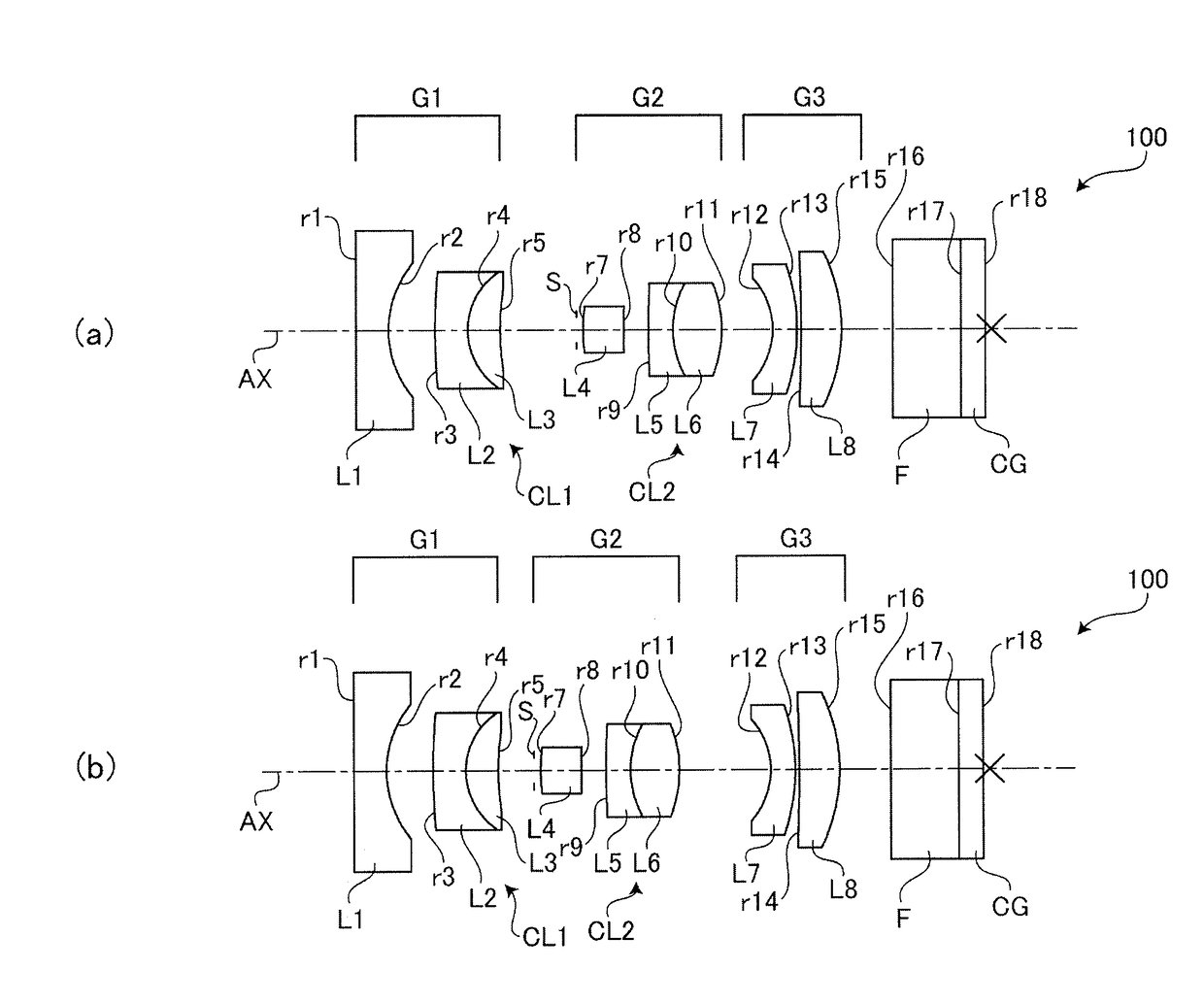
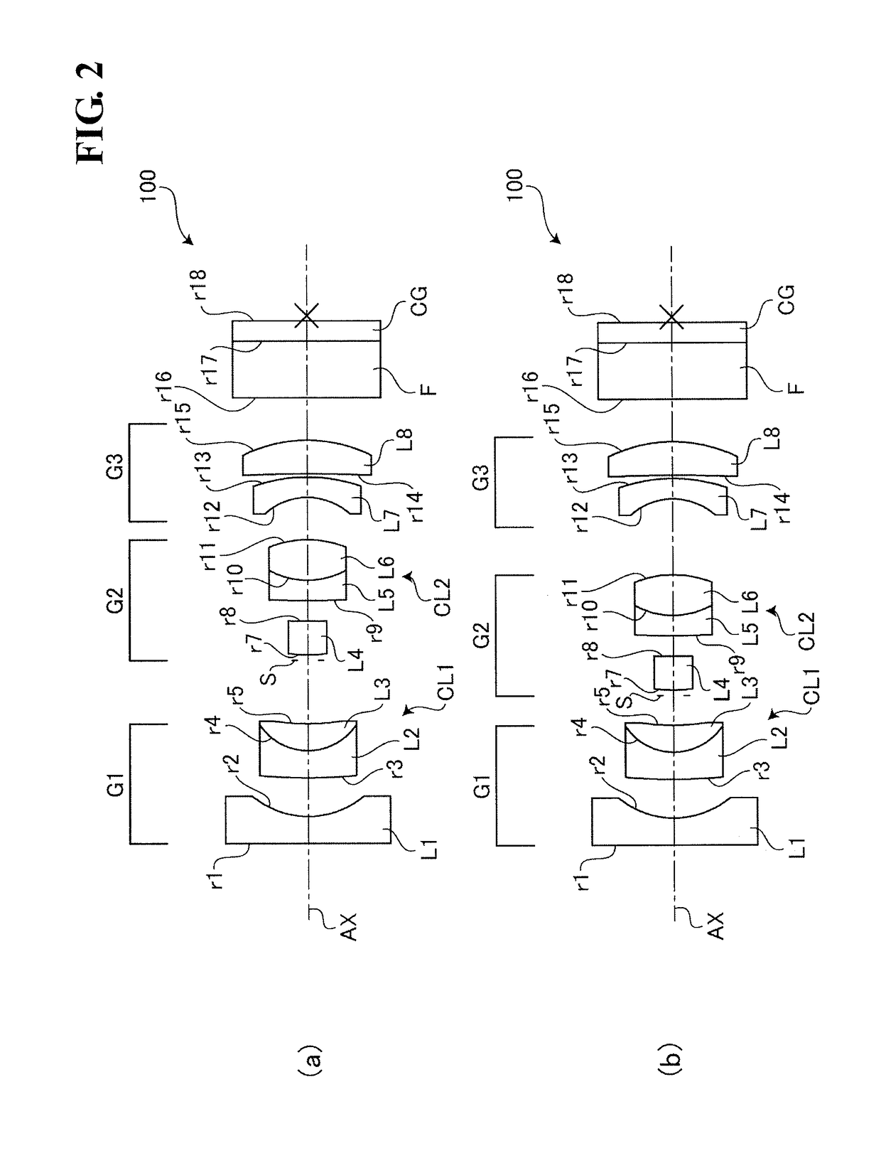
[0036]FIGS. 2(a) and 2(b) are cross-sectional views showing an arrangement of the endoscope magnification optical system 100 according to Working Example 1 of the present invention and optical components arranged downstream thereof. FIG. 2(a) is a cross-sectional view showing a lens arrangement when a magnification position is at a wide angle end. FIG. 2(b) is a cross-sectional view showing a lens arrangement when a magnification position is at a telephoto end.

[0037]As shown in FIG. 2, the endoscope magnification optical system 100 according to Working Example 1 has, in order starting from an object (subject) side, a first lens group G1, an aperture S, a second lens group G2, and a third lens group G3. The endoscope magnification optical system 100 according to Working Example 1 is configured to move the second lens group G2 in an optical axis direction AX with respect to the first lens group G1 and the third lens group G3, which are fixed lens groups, while a distance from the lens...

working example 2

[0058]FIGS. 4(a) and 4(b) are cross-sectional views showing an arrangement of the endoscope magnification optical system 100 according to Working Example 2 of the present invention and optical components arranged downstream thereof. FIG. 4(a) is a cross-sectional view showing a lens arrangement when the magnification position is at the wide angle end. FIG. 4(b) is a cross-sectional view showing a lens arrangement for when the magnification position is at the telephoto end.

[0059]As shown in FIG. 4, the endoscope magnification optical system 100 according to Working Example 2 has the same lens configuration as the endoscope magnification optical system 100 according to Working Example 1.

[0060]Graphs A to D in FIG. 5(a) are diagrams of various aberrations at the time when the magnification position is at the wide angle end in the endoscope magnification optical system 100 according to Working Example 2. Graphs A to D in FIG. 5(b) are diagrams of various aberrations at the time when the...

working example 3

[0063]FIGS. 6(a) and 6(b) are cross-sectional views showing an arrangement of the endoscope magnification optical system 100 according to Working Example 3 of the present invention and optical components arranged downstream thereof. FIG. 6(a) is a cross-sectional view showing a lens arrangement when the magnification position is at the wide angle end. FIG. 6(b) is a cross-sectional view showing a lens arrangement for when the magnification position is at the telephoto end.

[0064]As shown in FIG. 6, the endoscope magnification optical system 100 according to Working Example 3 has the same lens configuration as the endoscope magnification optical system 100 according to Working Example 1.

[0065]Graphs A to D in FIG. 7(a) are diagrams of various aberrations at the time when the magnification position is at the wide angle end in the endoscope magnification optical system 100 according to Working Example 3. Graphs A to D in FIG. 7(b) are diagrams of various aberrations at the time when the...


PUM


Abstract

An endoscope magnification optical system includes, in order starting from an object side, a first lens group having positive power, a second lens group having positive power, and a third lens group including at least a meniscus lens with a concave surface facing the object side and a positive lens, and the endoscope magnification optical system is configured to magnify an optical image by moving at least the second lens group in an optical axis direction with respect to the first lens group, which is a fixed lens group, while a distance from a lens surface located the closest to the object of the first lens group to an image plane is kept constant.

Description

TECHNICAL FIELD[0001]The present invention relates to an endoscope magnification optical system and an endoscope in which an endoscope magnification optical system is incorporated.[0002]In the field of medicine, endoscopes (fiberscopes or electronic scopes) are commonly known as devices for observing the interior of a body cavity of a patient, and are provided for practical use. In order to observe abnormalities in detail, some of these types of endoscopes are equipped with a magnification optical system having a magnification function.[0003]For example, Japanese Patent 3845331 (hereinafter written as “Patent Document 1”) discloses a specific configuration of an endoscope magnification optical system. The endoscope magnification optical system disclosed in Patent Document 1 includes, in order starting from an object side, a first lens group having negative power, a second lens group having positive power, a third 3 lens group having positive power, and a fourth lens group having neg...

Claims


Application Information

Patent Timeline
Patent Type & Authority Applications(United States)
IPC IPC(8): G02B23/24A61B1/00G02B15/15G02B15/167
CPCG02B23/2438G02B15/167G02B15/15A61B1/00188G02B15/143507A61B1/00G02B13/02G02B13/18G02B23/24G02B23/2415G02B23/243
Inventor FUJII, HIROAKI
Owner HOYA CORP
Why Eureka
Try Eureka