Pair of spectacle lenses for binocular vision, manufacturing method, supply system and supply program thereof

Active Publication Date: 2018-01-04
HOYA LENS THAILAND LTD
View PDF6 Cites 5 Cited by
  • Summary
  • Abstract
  • Description
  • Claims
  • Application Information

AI Technical Summary

Benefits of technology

This patent is about a technology that lets people see objects that are far away through special lenses.

Problems solved by technology

In this case, when the user sees an object at a distance through the distance portion of the spectacle lens, as illustrated in FIG. 5, the lines of sight would naturally be parallel if the user were not wearing the spectacle lenses, but the lines of sight of the user are forced to excessively diverge because of the presence of the base in prism.
However, when the user sees the object through the distance portion, an unintentional divergence is generated, and an unnecessary fatigue may be experienced.
What's worse is that this unintended prism becomes a base out prism which refracts the ray along the line of sight toward the ear of the user (outer horizontal direction).
And this additional convergence may cause unnecessary fatigue to the user.

Method used


Image

  • Pair of spectacle lenses for binocular vision, manufacturing method, supply system and supply program thereof
  • Pair of spectacle lenses for binocular vision, manufacturing method, supply system and supply program thereof
  • Pair of spectacle lenses for binocular vision, manufacturing method, supply system and supply program thereof

Examples


embodiment 1

[0079]This embodiment is described in the following sequence.

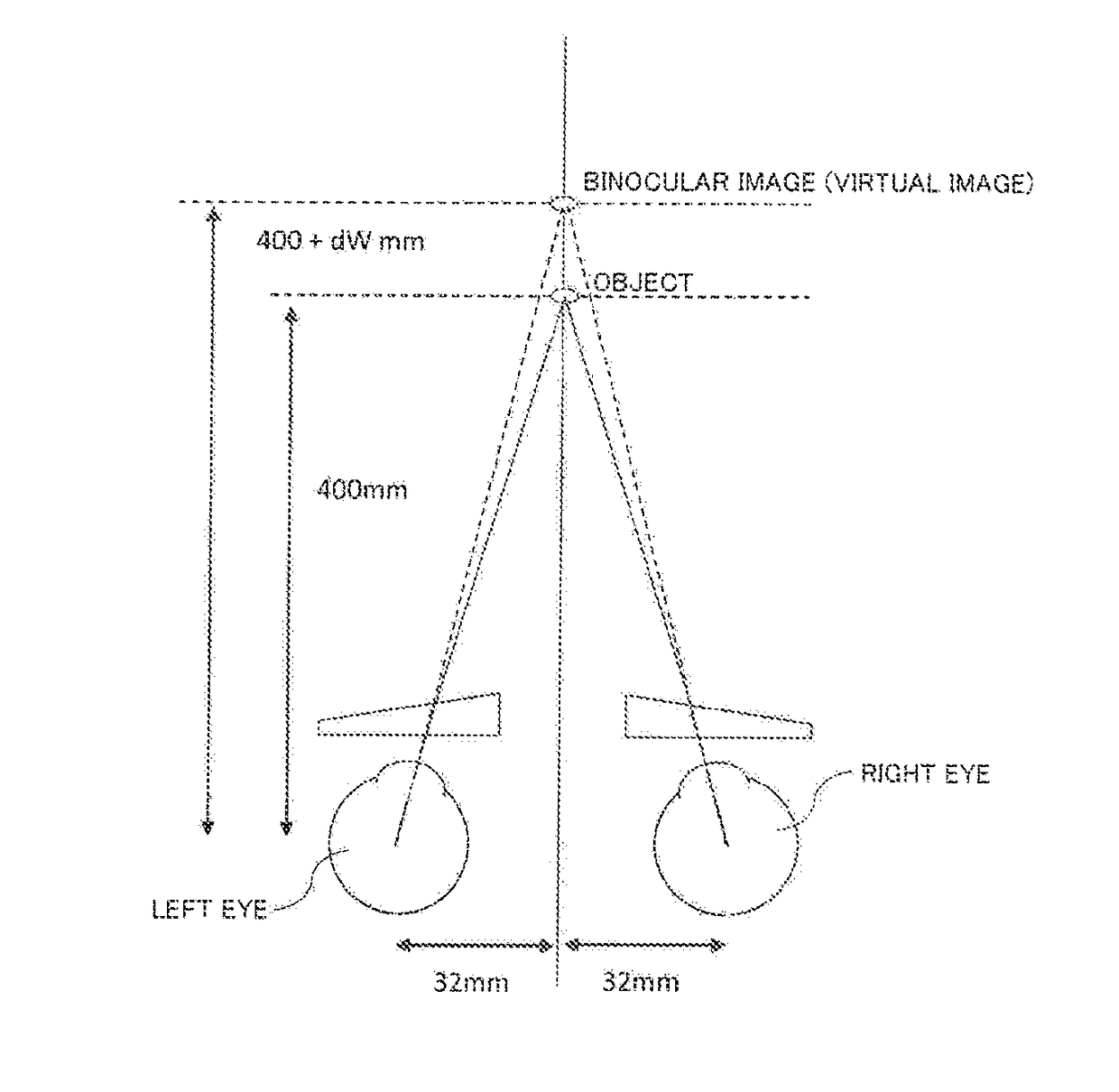
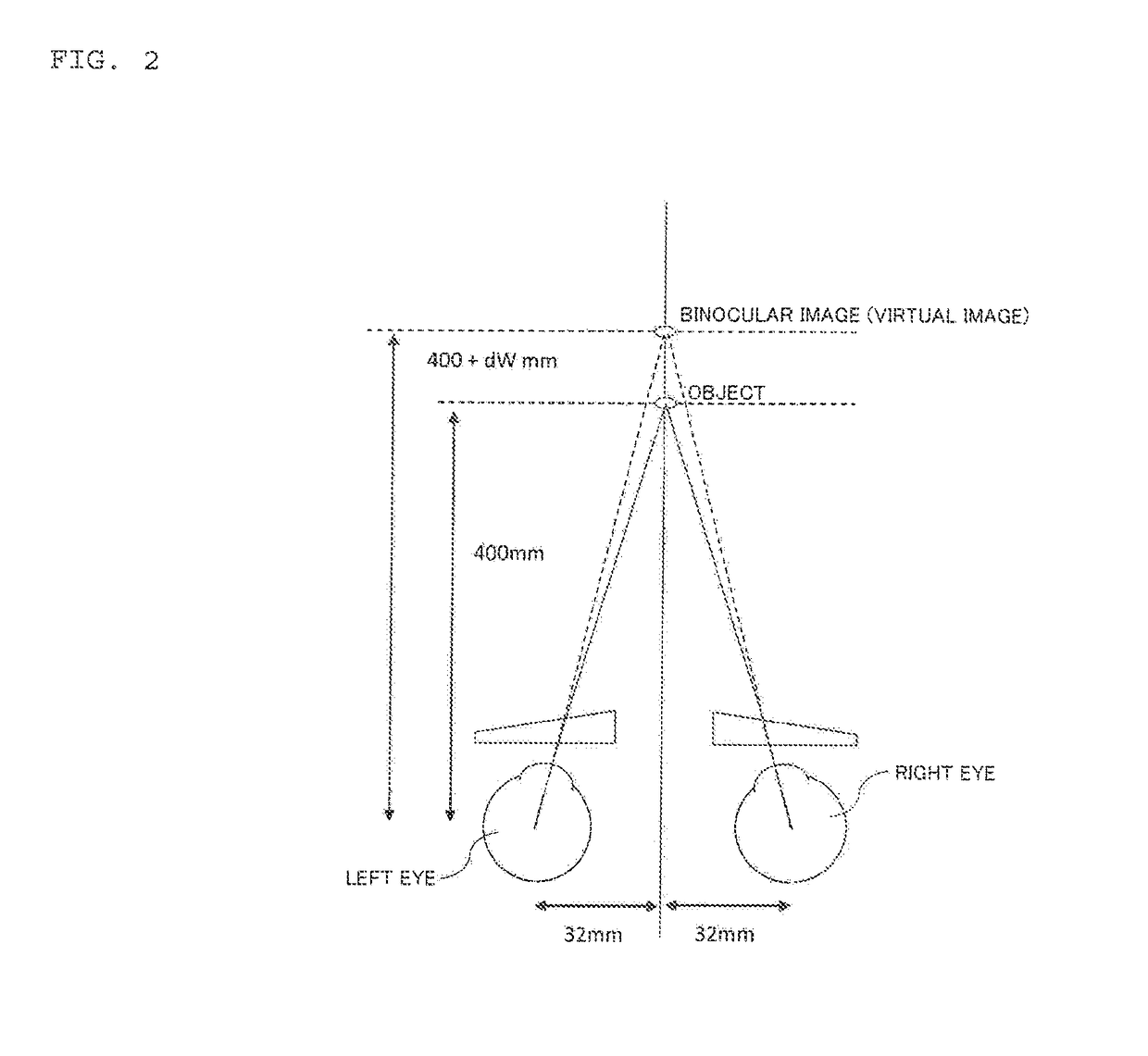
[0080]1. Technical idea of this invention[0081]1-1. Technical background[0082]1-2. Estimation of magnification change

[0083]2. Pair of spectacle lenses for binocular vision[0084]2-1. Configuration of spectacle lens[0085]2-2. Difference from prior art[0086]2-3. Determination method

[0087]In this description, it is assumed that the upper direction is a direction of top of the spectacle lens, and the lower direction is a direction of bottom of the spectacle lens. If a user moves their lines of sight from above to below through the spectacle lenses, the eyes converge inward.

[0088]Further, in this description, the inner horizontal direction is a direction toward the nose of the user, and the outer horizontal direction is a direction toward the ear of the user.

[0089]In this description, the horizontal direction is 0° or 180° in defining the astigmatic axis and the prism base direction, and an example when the horizontal direction ...

embodiment 2

3. Preferred Example of Shape of Base in Prism

[0144]In this embodiment, a preferred example of the shape of the base in prism is primarily described. Here redundant content of [Embodiment 1] is omitted.

[0145]This embodiment is described in the following sequence.[0146]3-1. Handling of divergence in front vision[0147]3-2. Handling of unintended base out prism

[0148]The spectacle lens according to this embodiment is not especially limited, as long as the spectacle lens has a portion in which power changes continuously (progressive portion). For example, the spectacle lens of this embodiment may be a progressive multifocal lens which includes a distance portion for viewing a distant area (e.g. infinity to 400 cm), and a near portion for viewing a near area (e.g. 100 cm or less), or a single vision lens which includes plus power and of which power changes while moving away from one region to view an object at a predetermined distance. Needless to say, the spectacle lens of this embodimen...

embodiment 3

[0234]In this embodiment, the above mentioned technology related to “a pair of spectacle lenses”, that is, a design method (manufacturing method) of the spectacle lens, a supply system of the spectacle lens, and a supply program of the spectacle lens is described.

[0235]This embodiment is described in the following sequence.

[0236]4. Design method (manufacturing method) of a pair of spectacle lenses for binocular vision[0237]4-1. Preparation step[0238]4-2. Design step[0239]4-3. Manufacturing step

[0240]5. Supply system of a pair of spectacle lenses for binocular vision[0241]5-1. Receiving unit[0242]5-2. Designing unit[0243]5-3. Transmitting unit

[0244]6. Supply program of a pair of spectacle lenses for binocular vision

4. Design Method (Manufacturing Method) of a Pair of Spectacle Lenses for Binocular Vision

[0245]A design method (manufacturing method) of the spectacle lens according to this embodiment is described. In the following description, the content already described in each of th...


PUM


Abstract

A technology concerning a pair of spectacle lenses for binocular vision. In each of the pair of spectacle lenses for binocular vision, when an inner horizontal direction of each of the spectacle lenses is a direction toward the nose of a user who wears the spectacle lenses, and an outer horizontal direction of the spectacle lenses is a direction toward an ear of the user, a portion for viewing an object at finite distance is provided in each of the pair of spectacle lenses for binocular vision and a shape of a base in prism is formed in the position such that a line of sight of a user viewing an object through the portion is directed to a direction that is different from a direction from the object.

Description

TECHNICAL FIELD[0001]The present invention relates to a pair of spectacle lenses for binocular vision, a manufacturing method, a supply system, and a supply program thereof.BACKGROUND ART[0002]Nowadays, various spectacle lenses for vision correction are known. For example, several examples can be put forward, such as a single vision lens in which one region for seeing an area at a predetermined distance is provided, a single vision lens in which power changes as view departs from the region, and a progressive power lens (a progressive multifocal lens in this description) which includes a portion (so-called progressive portion) where power changes continuously with respect to above two lenses.[0003]For example, a progressive power lens according to PTL 1 includes: a distance portion which has distance power for distance vision; a near portion which has near power for near vision; and a progressive portion which exists between the distance portion and the near portion. In the spectacl...

Claims


Application Information

Patent Timeline
IPC IPC(8): G02C7/06G02B27/01
CPCG02C7/061G02B2027/0136G02B27/0101G02C7/024G02C7/063G02C7/065G02C7/14G02C7/02G02C7/06G02C7/066
Inventor KAGA, TADASHIITO, AYUMUKOZU, KAZUMA
Owner HOYA LENS THAILAND LTD
Why Eureka
Try Eureka