Vibration actuator

a technology of vibration actuator and linear actuator, which is applied in the direction of magnetic circuits characterised by magnetic materials, dynamo-electric machines, and magnetic circuit shapes/forms/construction, etc., can solve problems such as restrictive problems, and achieve the effects of reducing the loss of magnetic flux, increasing the response speed of vibration actuator, and improving the power consumption of linear vibration actuator

Active Publication Date: 2018-01-04
JAHWA ELECTRONICS
View PDF9 Cites 1 Cited by
  • Summary
  • Abstract
  • Description
  • Claims
  • Application Information

AI Technical Summary

Benefits of technology

[0028]In addition, it is possible to increase a response speed of a vibration actuator by adjusting design variables in relation to electromagnetic characteristics, rather than a mechanical restoring force.
[0029]Further, according to an embodiment of the present disclosure, a neodymium magnet of the present disclosure is plated with a magnetic substance such as zinc and improves power consumption of the linear vibration actuator by reducing a loss of magnetic flux.
[0030]In addition, the zinc-plated neodymium magnet of the present disclosure may improve sensitivity quality for vibrations of a portable terminal by enlarging an effective frequency bandwidth of the linear vibration actuator.
[0031]Moreover, it is possible to solve a problem that a magnetic fluid deviates from its original position to move toward a permanent magnet and thus is not located at a position for performing its damping function.
[0032]Further, in the present disclosure, embodiments of the present disclosure may be applied in combination to provide a vibration actuator more suitable for various needs of users by optimally enlarging a frequency band and improving vibration characteristics, center frequency shifting, and a response speed, demanded for haptic operation.

Problems solved by technology

However, since the rear-earth metal is rapidly oxidized and corroded in the art, the surface of the neodymium magnet is coated.
Also, the loss of magnetic flux gives an influence on the magnetic force of the neodymium magnet and also gives a restrictive problem in providing a vibration characteristic in a low-frequency band which is demanded in realizing haptic vibrations.

Method used


Image

  • Vibration actuator
  • Vibration actuator
  • Vibration actuator

Examples


Embodiment Construction

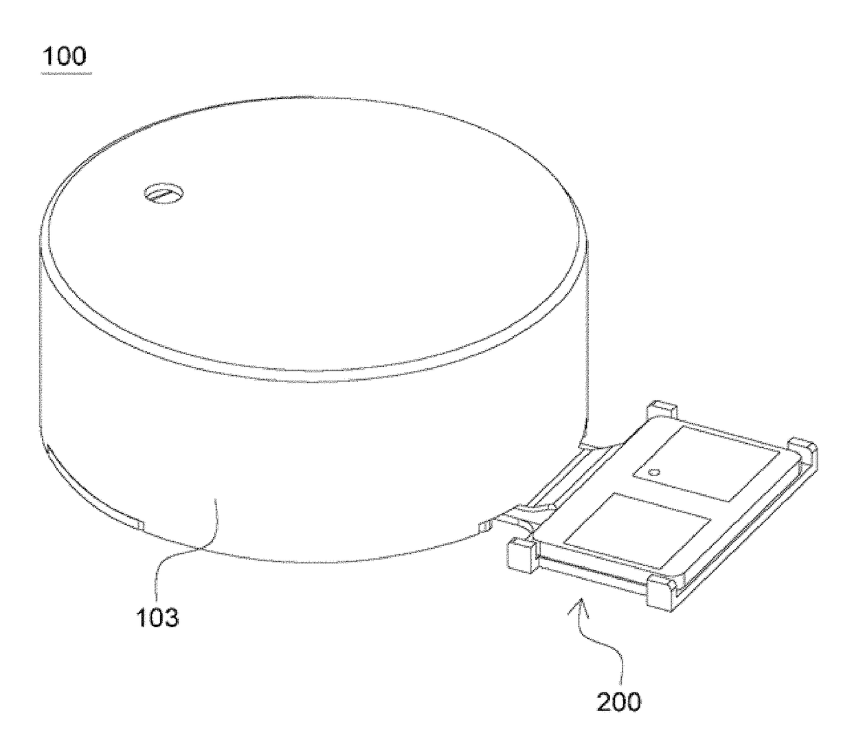
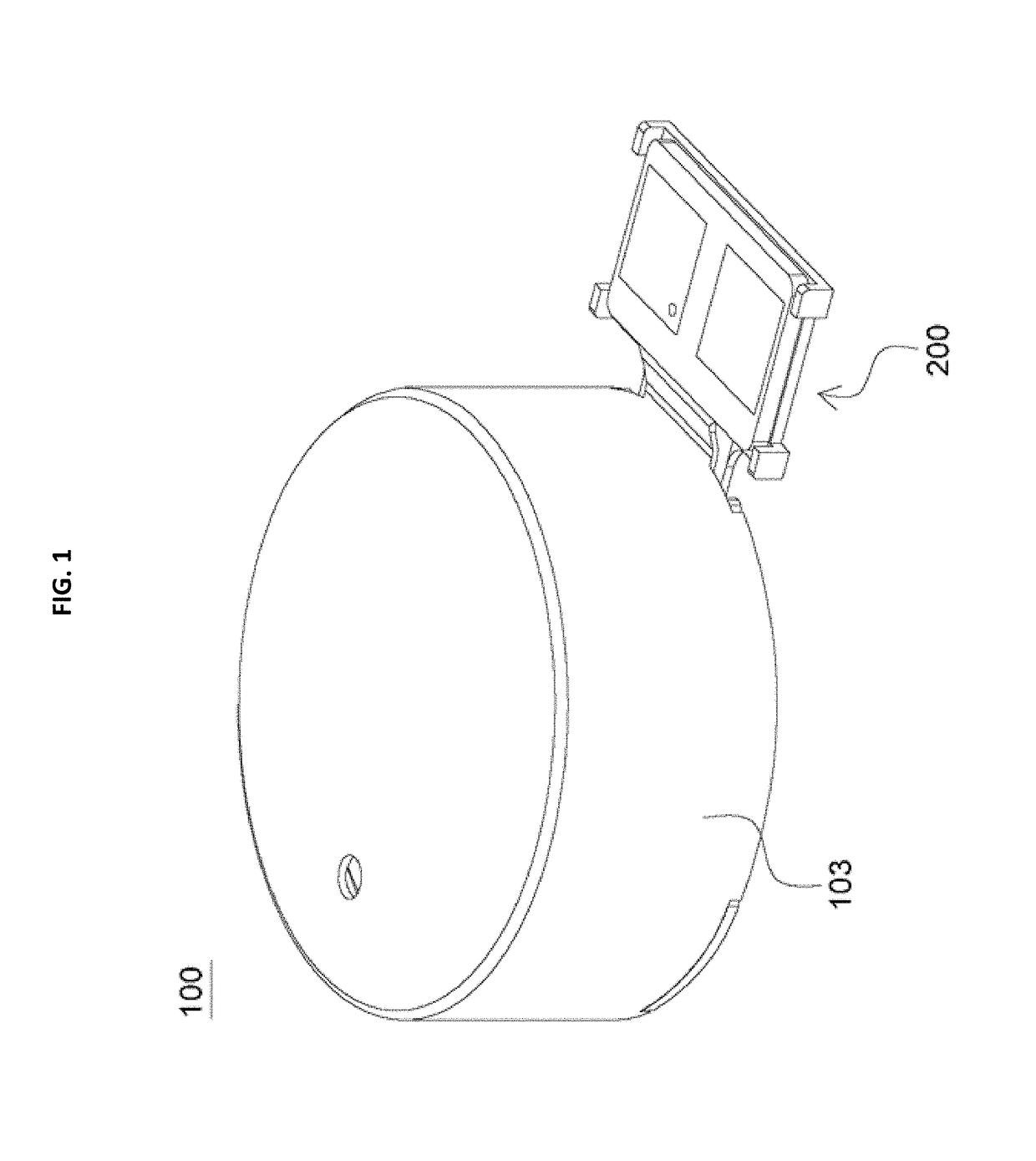
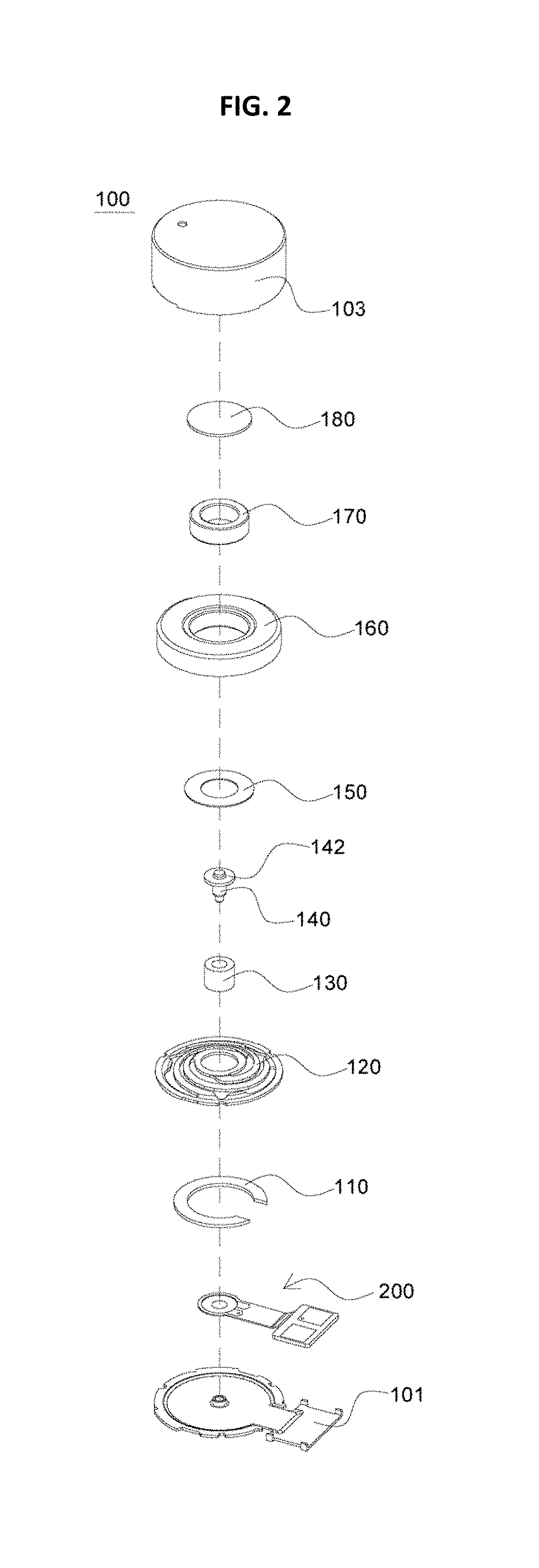
[0043]FIG. 1 is a perspective view showing a vibration actuator according to an embodiment of the present disclosure, FIG. 2 is an exploded perspective view showing the vibration actuator according to an embodiment of the present disclosure, and FIG. 3 is a side-sectional view showing the vibration actuator according to an embodiment of the present disclosure.

[0044]Referring to FIG. 1 to FIG. 3, a vibration actuator 100 according to an embodiment of the present disclosure may include a bracket 101 coupled to a case 103 to form an inner space; a stator having a circuit board 200 coupled to an upper surface of the bracket 101, a coil 130 connected to the circuit board 200, and a yoke 140 disposed in the coil 130; a vibrator having a permanent magnet 170 disposed at an outer side of the coil 130 and a weight 160 coupled to an outer circumference of the permanent magnet 170; and an elastic member 120 configured to connect the stator and the vibrator and elastically support the vibrator....


PUM


Abstract

A vibration actuator includes a bracket coupled to a case to form an inner space; a stator having a circuit board coupled to an upper surface of the bracket, a coil connected to the circuit board, and a yoke provided in the coil; a vibrator having a permanent magnet disposed at an outer side of the coil and a weight coupled to an outer circumference of the permanent magnet; an elastic member configured to connect the stator and the vibrator and elastically support the vibrator; and a non-magnetic damper provided between the weight and the elastic member.

Description

CROSS-REFERENCE TO RELATED APPLICATION AND CLAIM OF PRIORITY[0001]The present application claims priority to Korean Patent Application No. 10-2016-0103746 filed on Aug. 16, 2016 and No. 10-2016-0083740 filed on Jul. 1, 2016 in the Korea Intellectual Property Office, the disclosures of which are incorporated herein by reference.BACKGROUND1. Technical Field[0002]The present disclosure relates to a vibration actuator, and more particularly, to a vibration actuator capable of adjusting a resonance frequency band as desired by a user, improving vibration power and response speed, and suppressing vibration and noise caused by collision of internal components by means of an adjusted shape of a wing portion of a yoke.2. Background Art[0003]Recently, a linear vibration actuator used as a silent receiver of a portable terminal copes with a slim design of the portable terminal since it has a short stroke distance (up and down movement rather than rotation) and ensures rapid vibration at a star...

Claims


Application Information

Patent Timeline
Patent Type & Authority Applications(United States)
IPC IPC(8): H02K33/02H02K1/02H02K1/12H02K1/34
CPCH02K33/02H02K1/34H02K1/12H02K1/02H02K2213/03
Inventor CHOI, NAM JINJO, KYUNG HOONSHIM, SOON KOOCHONG, YOUNG BINLEE, WON GOOKLEE, MIN GOO
Owner JAHWA ELECTRONICS
Why Eureka
Try Eureka