
Method for bonding at least partially overlapping material layers and automatic bonding apparatus for performing the method

a technology of material layers and automatic bonding, applied in the field of methods, can solve the problems of large mass of heating wedges used, and achieve the effects of convenient high surface temperature, quick reaction time, and convenient heating and cooling

Active Publication Date: 2018-01-18
LEISTER TECHNOLOGIES
View PDF11 Cites 1 Cited by
  • Summary
  • Abstract
  • Description
  • Claims
  • Application Information

AI Technical Summary

Benefits of technology

This patent describes a heating device that uses a heating resistor to provide a safe and reliable way to control the heating of an object. The device uses low safety voltage to prevent accidental touches and quickly cools down when the operating voltage is turned off to prevent burn injuries. The electrical power of the heating resistor is determined by measuring the voltage drop and current running through the heating resistor, which ensures accurate and safe heating control.

Problems solved by technology

It is perceived to be a disadvantage of known automatic heating wedge bonding apparatuses and the bonding methods performed therewith that the heating wedges used have a relative large mass which prevents quick heating and cooling of the heating wedge with a necessary adaptation of temperature or power of the heating wedge during the welding process which is required for example due to occurring velocity changes during welding in order to assure a constant weld quality.

Method used


Image

  • Method for bonding at least partially overlapping material layers and automatic bonding apparatus for performing the method
  • Method for bonding at least partially overlapping material layers and automatic bonding apparatus for performing the method
  • Method for bonding at least partially overlapping material layers and automatic bonding apparatus for performing the method

Examples


Embodiment Construction

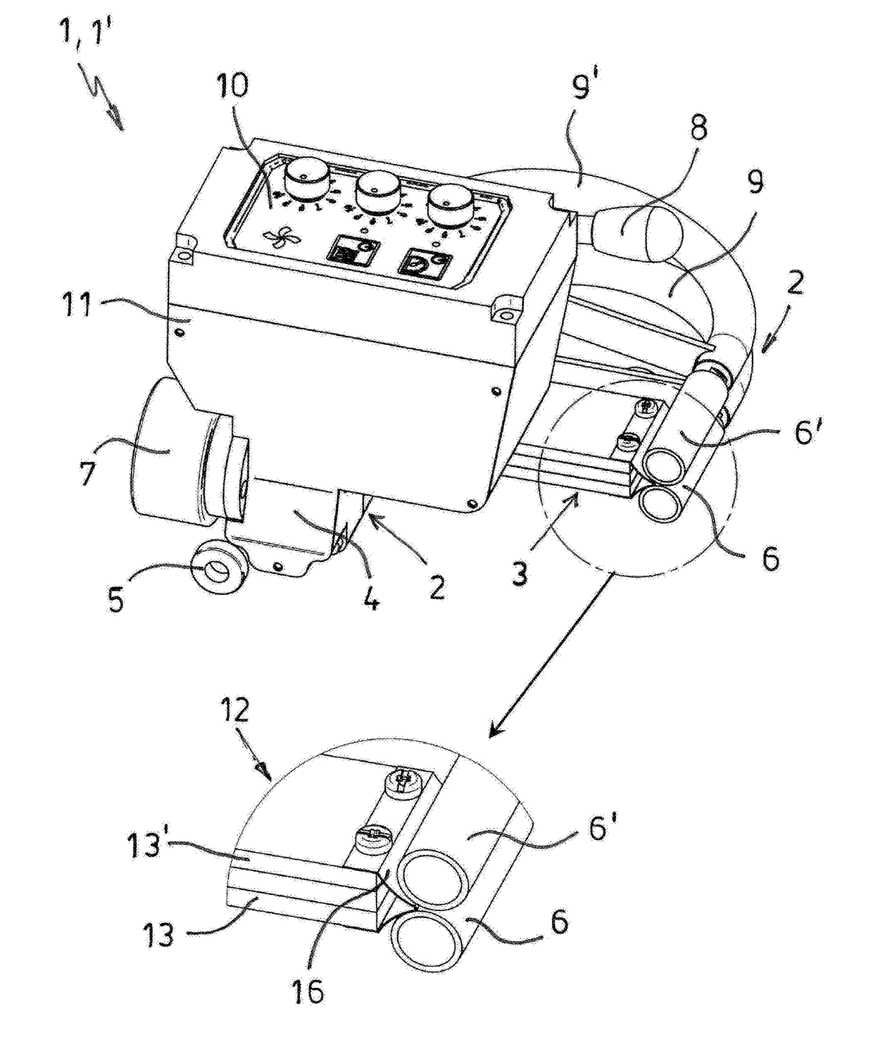
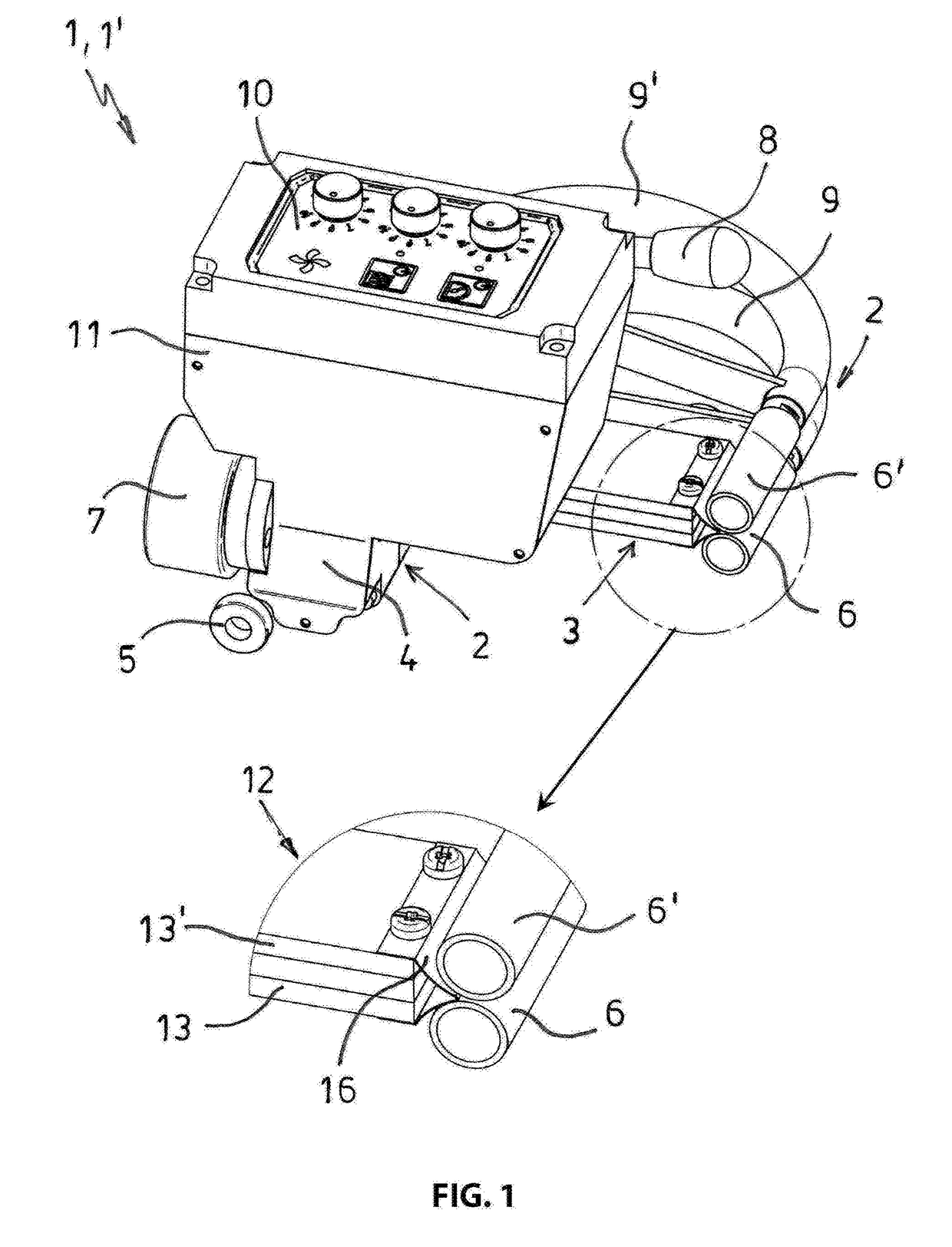
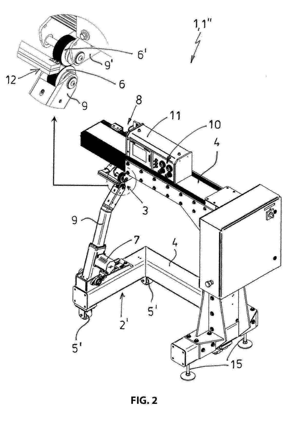
[0037]FIG. 1 illustrates an embodiment of an automatic bonding apparatus 1 according to the invention which is configured as a mobile self-propelled automatic welding apparatus 1′ for overlapping edge welding of thermoplastic synthetic material webs that are not illustrated in the drawing figure. The automatic welding apparatus 1′ includes a chassis 2 with a contact heating arrangement 3 arranged at the chassis for edge melting of synthetic material webs, wherein the chassis 2 has a carrier frame 4 at which plural running rollers 5 that are offset from each other and two opposite contact pressure and feed rollers 6, 6′ are arranged. The lower contact pressure and feed roller 6 is fixated in place and the other upper contact pressure and feed roller 6′ is pivot ably supported. The automatic welding apparatus 1′ furthermore includes a drive arrangement 7 that is only partially illustrated in the drawing figure for the contact pressure and feed rollers 6, 6′. The running rollers 5 are ...


PUM

PropertyMeasurementUnit
thicknessaaaaaaaaaa
thicknessaaaaaaaaaa
massaaaaaaaaaa

Abstract

An automatic bonding apparatus and a method for thermally induced seam bonding of weldable and / or gluable flat flexible material layers with each other which are each configured as a material web, material band and / or material piece and arranged so that they overlap at least partially wherein the bonding is performed by an electrically controlled contact heating arrangement through a heating wedge welding method. A temperature and / or a power of the heating wedge which is formed by a thin folded steel sheet blank is controlled as a function of a relative velocity between the material layers and the automatic bonding apparatus. This is performed so that a thermal energy that is transferred from the heating wedge to the material layers to be glued is kept constant. For this purpose the relative velocity is detected and the power of the heating wedge is automatically adjusted when the relative velocity changes.

Description

RELATED APPLICATIONS[0001]This application claims priority from and incorporates by reference European Patent Application 16 179 503.4 filed on Jul. 14, 2016.FIELD OF THE INVENTION[0002]The invention relates to a method for thermally induced seam bonding of weldable and / or gluable flat flexible material layers with each other, wherein the material layers are configured as a material web, a material band and / or a material piece and are arranged at least partially overlapping using an automatic bonding apparatus using at least one electrical contact heating arrangement that is arranged at a carrier frame of the automatic bonding apparatus with a directly electrically powered and heatable heating wedge for locally heating at least one of the material layers to be bonded to a bonding temperature and at least one contact pressure and feed roller arranged at the carrier frame and driven by an electric motor for locally compressing a heated material portion of the material layer, wherein a...

Claims


Application Information

Patent Timeline
Patent Type & Authority Applications(United States)
IPC IPC(8): B29C65/22B29C65/00B29C65/10B29C65/78
CPCB29C65/228B29C65/10B29C65/7835B29C66/71B29C66/82261B29C66/80B29C66/1122B29C66/91651B29L2031/723B29C65/20B29C65/224B29C65/30B29C66/43B29C66/73921B29C66/8122B29C66/81417B29C66/8167B29C66/83413B29C66/8362B29C66/86521B29C66/91231B29C66/9131B29C66/91421B29C66/934B29C66/961B29C66/9672B29C66/91213B29C66/932B29L2031/30B29C66/8187B29L2031/485B29C65/62B29C66/0384B29C66/86523B29C66/9241B29K2905/12
Inventor LOETSCHER, ROMANNIEDERBERGER, ADOLFHORAT-FAESSLER, PASCAL
Owner LEISTER TECHNOLOGIES
Learn More