Motion-measuring system of a machine and method for operating the motion-measuring system

Active Publication Date: 2018-01-18
CARL ZEISS IND MESSTECHN GMBH
View PDF6 Cites 22 Cited by
  • Summary
  • Abstract
  • Description
  • Claims
  • Application Information

AI Technical Summary

Benefits of technology

[0058]Preferably, a capturing structure in the frequency domain therefore has the property of having no zero within a frequency range which begins at the frequency zero, but which does not include the frequency zero, and which ends at a predefined maximum frequency. That is to say that the function value of the function in the frequency domain, which can also be referred to as amplitude, is greater than zero within the frequency range. The maximum frequency is predefined in particular such that it is not less than the Nyquist frequency of the camera. In particular, the maximum frequency is equal to the Nyquist frequency of the camera or greater than the Nyquist frequency of the camera, but is not more than double the Nyquist frequency of the camera. A capturing structure without zeros in the frequency domain has the advantage that the convolution of the capturing structure is accomplished by means of an operation relative to the frequency domain and can therefore be carried out in a simple manner. In the case of zeros, by contrast, the operation is not defined in the frequency domain.
[0059]In one development of this class of capturing structures, with which the convolution can be carried out reliably and accurately, the function value of the position function of the capturing structure transformed into the frequency domain is greater than a predefined minimum value in the entire frequency range from zero up to the maximum frequency. In particular, the predefined minimum value is greater than a statistical fluctuation (noise) of the image values that is brought about by the recording of the camera image and by the evaluation of the camera image by an evaluation device of the machine. To put it more generally, the predefined minimum value is greater than a statistical fluctuation amplitude of image values of the recording image, said statistical fluctuation amplitude being brought about by the recording of the recording image and by a determination of the speed. The fluctuation amplitude therefore corresponds in particular to the statistical fluctuation amplitude of that capturing structure which is beset by additional noise and which, under the theoretical assumption of

Problems solved by technology

In the event of a relative movement of the first and second parts, a problem that is generally known when photographing moving objects occurs, namely the blurring of structures in the recorded camera image.
However, care must be taken to ensure sufficient illumination in order that the signal-to

Method used


Image

  • Motion-measuring system of a machine and method for operating the motion-measuring system
  • Motion-measuring system of a machine and method for operating the motion-measuring system
  • Motion-measuring system of a machine and method for operating the motion-measuring system

Examples


Embodiment Construction

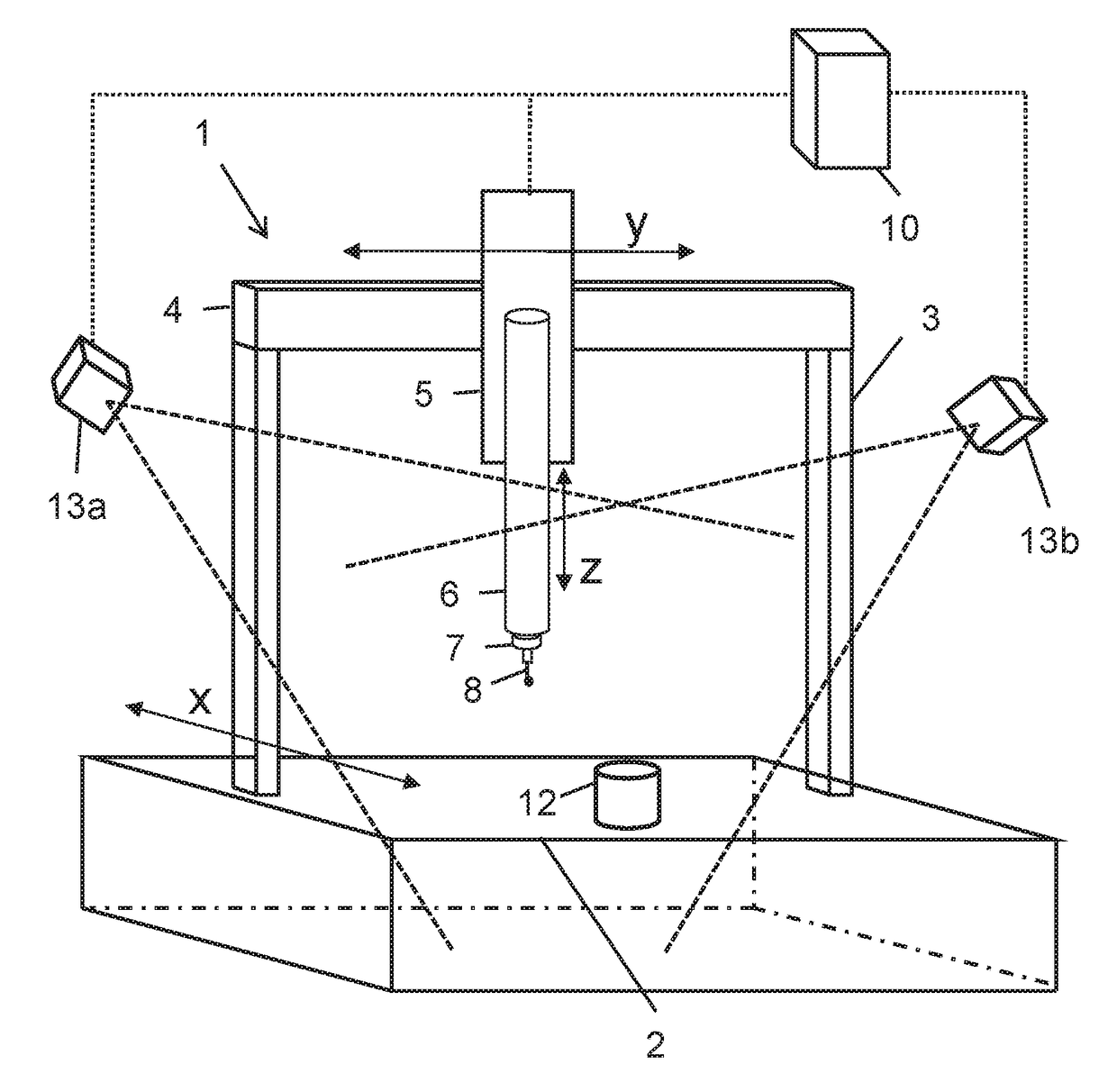
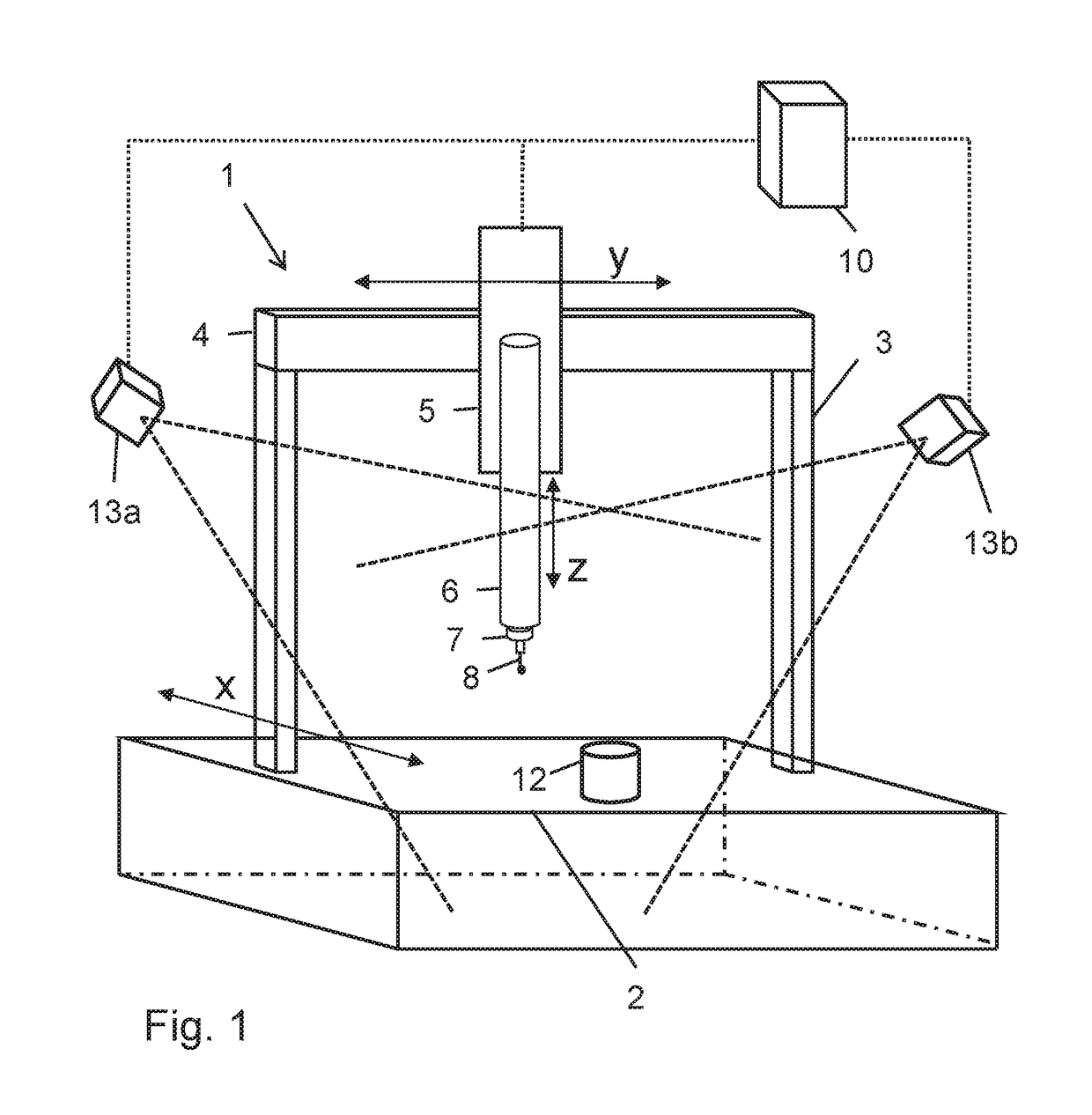
[0137]FIG. 1 shows a coordinate measuring machine 1 of gantry design. The gantry 3, which is movable in the X-direction of a cartesian coordinate system of the CMM 1, is arranged on a measuring table 2 of the CMM 1. A slide 5 can be moved in the Y-direction of the coordinate system along a transverse carrier 4 of the gantry 3. Furthermore, a sleeve 6 is arranged on the slide 5 movably in the Z-direction of the coordinate system. A measuring head 7, i.e. a sensor, carrying a probe 8, is secured on the lower end of the sleeve 6. No drives are illustrated in the simplified illustration.

[0138]As is illustrated schematically in FIG. 1, the coordinate measuring machine 1 comprises a control and evaluation device 10, which is for example part of a commercially available computer or computer specifically configured for the operation of the CMM, said computer being equipped with software for the operation of the CMM 1. The control and evaluation device 10 is connected to the movable parts of...


PUM


Abstract

A method for operating a motion-measuring system of a machine, such as a coordinate-measuring device or a machine tool. An image-recording device arranged on a first part of the machine records at least one recorded image of a second part of the machine. The first part and the second part can be moved in relation to each other. A capturing structure, which is formed by the second part and/or which is arranged on the second part, is captured by the at least one recorded image, and, by using information about an actual appearance of the capturing structure, a speed of the relative motion of the first part and the second part is determined from differences of the at least one recorded image from the actual appearance of the capturing structure.

Description

CROSS-REFERENCES TO RELATED APPLICATIONS[0001]This application is a continuation of international patent application PCT / EP2016 / 056928, filed on Mar. 30, 2016 designating the U.S., which international patent application has been published in German and claims priority from German patent application DE 10 2015 205 738.0, filed on Mar. 30, 2015. The entire contents of these prior applications are incorporated herein by reference.BACKGROUND OF THE INVENTION[0002]The invention relates to a motion-measuring system of a machine, a machine comprising a motion-measuring system, a method for operating a motion-measuring system of a machine, and a method for operating a machine comprising a motion-measuring system.[0003]Machines, such as e.g. coordinate measuring machines or machine tools, usually have a movable part, which e.g. carries a sensor for capturing coordinates of a workpiece or carries a processing tool for processing a workpiece. The movable part is therefore a sensor carrier, in ...

Claims


Application Information

Patent Timeline
IPC IPC(8): G01B5/008B23Q17/24
CPCG06T7/248G01B5/008B23Q17/2409G06T2207/30164G01B11/002G01B21/042
Inventor HAVERKAMP, NILSSEITZ, DOMINIKTEUBER, TANJAOMLOR, LARS
Owner CARL ZEISS IND MESSTECHN GMBH
Why Eureka
Try Eureka