Apparatus for measuring bioimpedance and electrode-side board thereof

a bioimpedance and electrode-side board technology, applied in the field of bioimpedance measurement apparatus, can solve the problems of high-frequency component of current generated by current source leakage and measurement bioimpedance error, and achieve the effect of minimizing loss and leakage of curren

Active Publication Date: 2018-01-25
INBODY
View PDF2 Cites 0 Cited by
  • Summary
  • Abstract
  • Description
  • Claims
  • Application Information

AI Technical Summary

Benefits of technology

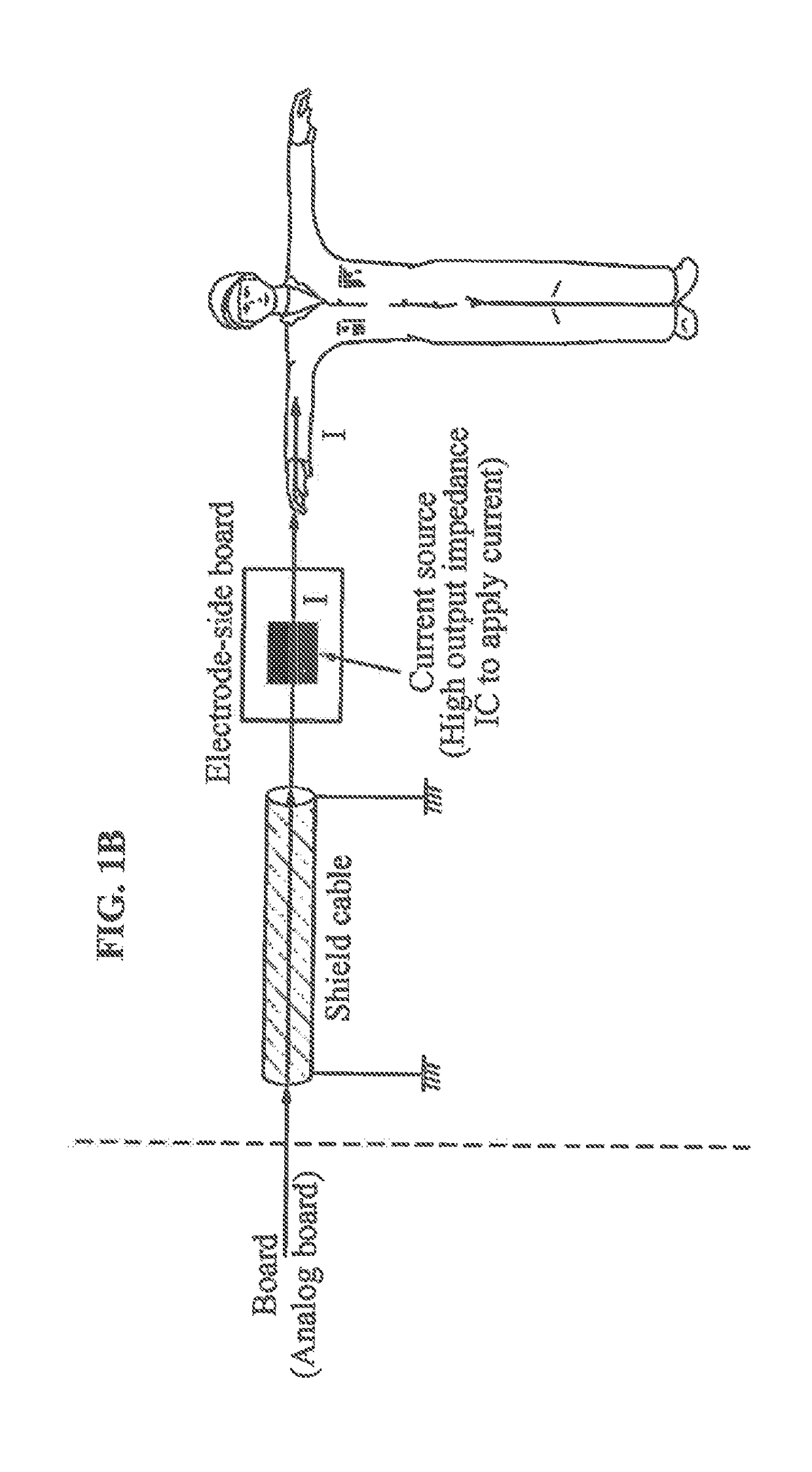
[0009]An aspect provides a bioimpedance measurement apparatus that may minimize a loss and leakage of a current applied to a current electrode that is in contact with a body, by disposing a current source configured to apply a current to the current electrode in an electrode-side board.
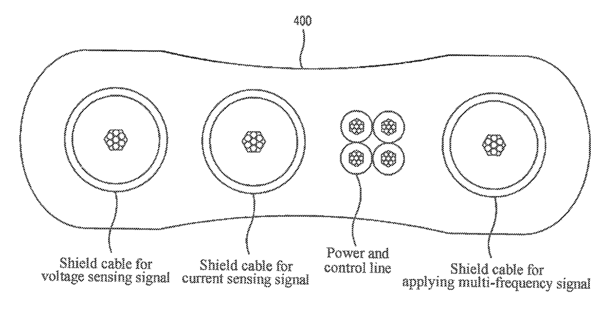
[0010]Another aspect also provides a bioimpedance measurement apparatus that may minimize a loss and leakage of a signal when the signal is transferred between an electrode-side board and a board (for example, an analog board), by connecting the electrode-side board and the board via a shield cable. The electrode-side board may include a current source configured to apply a current to a current electrode, and the board may include a processing circuit configured to process a signal acquired through the electrode-sideboard and a frequency signal generator configured to provide a multi-frequency signal to the electrode-side board.
[0011]Still another aspect also provides a bioimpedance measurement apparatus that may measure a bioimpedance of a target regardless of a loss and leakage of a current applied to a current electrode, by disposing, in an electrode-side board, a current source configured to apply a current to the current electrode and a current detection circuit configured to detect a current generated by the current source.

Problems solved by technology

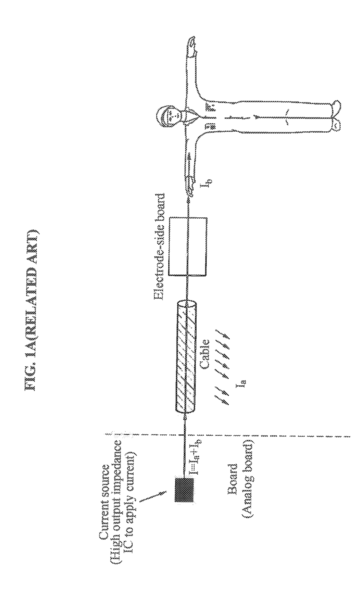
However, a high-frequency component of the current generated by the current source may leak while passing through the cable.
When the bioimpedance is measured by measuring the current generated by the current source, the measured bioimpedance may include an error caused by currents that are lost and leaks.

Method used


Image

  • Apparatus for measuring bioimpedance and electrode-side board thereof
  • Apparatus for measuring bioimpedance and electrode-side board thereof
  • Apparatus for measuring bioimpedance and electrode-side board thereof

Examples


Embodiment Construction

[0034]The following structural or functional descriptions of example embodiments described herein are merely intended for the purpose of describing the example embodiments described herein and may be implemented in various forms. However, it should be understood that these example embodiments are not construed as limited to the illustrated forms and include all changes, equivalents, and replacements within the idea and the technical scope of the disclosure.

[0035]Although terms of “first,”“second,” and the like are used to explain various components, the components are not limited to such terms. These terms are used only to distinguish one component from another component. For example, a first component may be referred to as a second component, or similarly, the second component may be referred to as the first component within the scope of the present disclosure.

[0036]When it is mentioned that one component is “connected” or “accessed” to another component, it may be understood that ...


PUM


Abstract

A bioimpedance measurement apparatus is provided. The bioimpedance measurement apparatus includes an electrode-side board that is configured to be connected to a current electrode in contact with a body and that includes a current source configured to apply a current to the current electrode. The electrode-side board may be connected via a cable to a board in which a processing circuit configured to process a signal acquired through the electrode-side board and / or a frequency signal generator configured to provide a predetermined frequency signal to the electrode-side board are located.

Description

CROSS-REFERENCE TO RELATED APPLICATION[0001]This application claims the benefit of Korean Patent Application No. 10-2016-0093283, filed on Jul. 22, 2016, in the Korean Intellectual Property Office, the disclosure of which is incorporated herein by reference.BACKGROUND1. Field of the Invention[0002]One or more example embodiments relate to a bioimpedance measurement apparatus, and more particularly, to a configuration of an electrode-side board to which an electrode having a bioimpedance is connected.2. Description of the Related Art[0003]Recently, a bioimpedance measurement apparatus for measuring a bioimpedance is widely used to analyze a characteristic or state of a body as well as a body fat, and the like. For example, due to a difference in a moisture distribution between muscles and fats of a body, a body water content, a muscle mass and a fat mass of a target may be analyzed using a simple and reliable scheme by measuring a bioimpedance of the body.[0004]A bioimpedance measure...

Claims


Application Information

Patent Timeline
Patent Type & Authority Applications(United States)
IPC IPC(8): A61B5/053A61B5/0402A61B5/117H03H7/38
CPCA61B5/053A61B5/117A61B5/0402H03H7/38A61B5/6833A61B5/0537A61B5/7225A61B2562/182A61B5/259A61B5/276A61B5/30A61B5/318A61B5/0531
Inventor WOO, JONG BUM
Owner INBODY
Why Eureka
Try Eureka