Miniaturized DNA microarray for small-volume sample processing

a dna microarray and small-volume technology, applied in biochemistry apparatus and processes, laboratory glassware, centrifuges, etc., can solve the problems of long incubation time and effort to conserve, and achieve the effect of reducing the risk of sample loss, and accelerating reaction tim

Pending Publication Date: 2021-07-22
CHARLES STARK DRAPER LABORATORY
View PDF2 Cites 0 Cited by
  • Summary
  • Abstract
  • Description
  • Claims
  • Application Information

AI Technical Summary

Benefits of technology

[0013]Suitable conditions (e.g., incubation time and temperature) and reagents (e.g., incubation buffer and wash buffers) for a specific hybridization reaction between the sample oligonucleotide and arrayed oligonucleotide probes are well known to those of skill in the art. As described herein, because of the small sample size required for the mini-microarrays of the present invention, reactions time can be accelerated. Moreover, the mini-microarray assemblies, apparatuses and devices as described herein are designed for optical detection of a hybridization reaction (e.g., using fluorescent tags) and can be adapted for read-out by standard optical means.
[0014]The advantages of the present invention are many. The present approach includes the construction of a mini-microarray to enable low-volume analysis and conservation of high value samples. There are numerous technical benefits to mini-arrays over traditional microarrays. Traditional microarrays represent higher risk of sample loss through evaporation due to the relatively large surface area and temperatures applied to allow for the hybridization reaction to take place. As described herein, the mini-microarray can be enclosed or encapsulated in a chamber / container to minimize sample volume and loss. In some embodiments, the mini-microarray will encapsulate the target sample in a sealed chamber that will fit into a microcentrifuge tube, (e.g., a 1.5-2 milliliter (ml) tube) allowing for centrifugation and recovery of unhybridized sample, which can be analyzed downstream. High-stringency washes that allow for high specificity of hybridization can be also be recovered. Additionally, a dehybridization reaction can also be carried out in the chamber, allowing further analysis of the specific hybridization events after scanning of the mini-array spots.
[0015]The present approach enables the combination of the aspects of the mini-microarray with microfluidic and optical hardware. The present microfluidic device can be comprised of a fluid channel that will sit atop a high-density microarray. The microarray probes can be spotted on a transparent surface (i.e., a glass slide) that will form the bottom wall of the channel. Closed-loop pressure-driven flow will enable the sample to be passed over the array (e.g., in a cyclic or serpentine manner as dependent on the channel formation) to maximize interaction between sample oligonucleotides / DNA of interest and nucleic acid probes. This will reduce incubation time and will increase overall binding efficiency.
[0016]In addition, the high specificity of traditional microarray assays will be maintained by the increased interaction between target sample and microarray probes. Completely enclosing the liquids will enable handling of small aqueous sample volumes (e.g., about or less than 10 μL). Following the incubation period, any un-hybridized sample can be extracted from the device for further downstream processing.
[0017]The hardware components will provide a multiplexed, optical readout with high sensitivity and specificity, enabling interrogation of samples and permitting recovery of both hybridized and non-hybridized samples to allow downstream testing in further assays.

Problems solved by technology

Some limitations of conventional DNA microarray assays include the following: (1) the geometry and probe layout of the array lead to lengthy incubation times; (2) large target sample volumes are required: (3) no effort is made to conserve or to recover the sample; and (4) optical readout is a separate step which typically requires a specialized scanner.

Method used


Image

  • Miniaturized DNA microarray for small-volume sample processing
  • Miniaturized DNA microarray for small-volume sample processing
  • Miniaturized DNA microarray for small-volume sample processing

Examples


example 1

on of a Miniaturized DNA Microarray

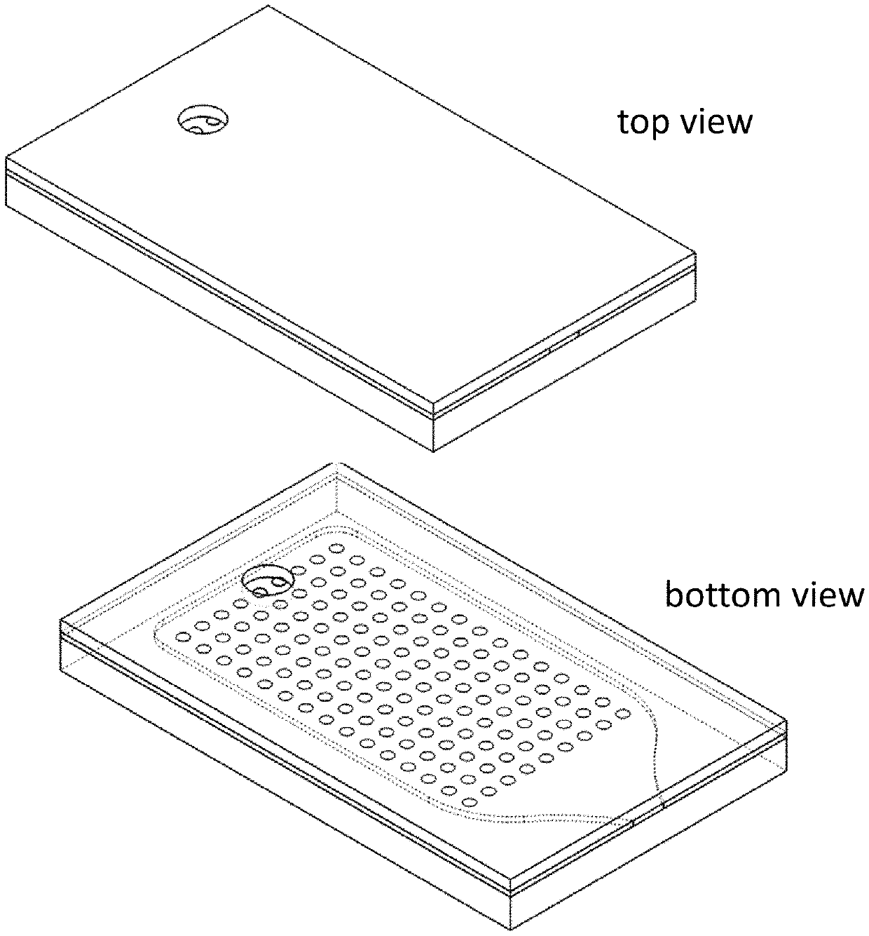
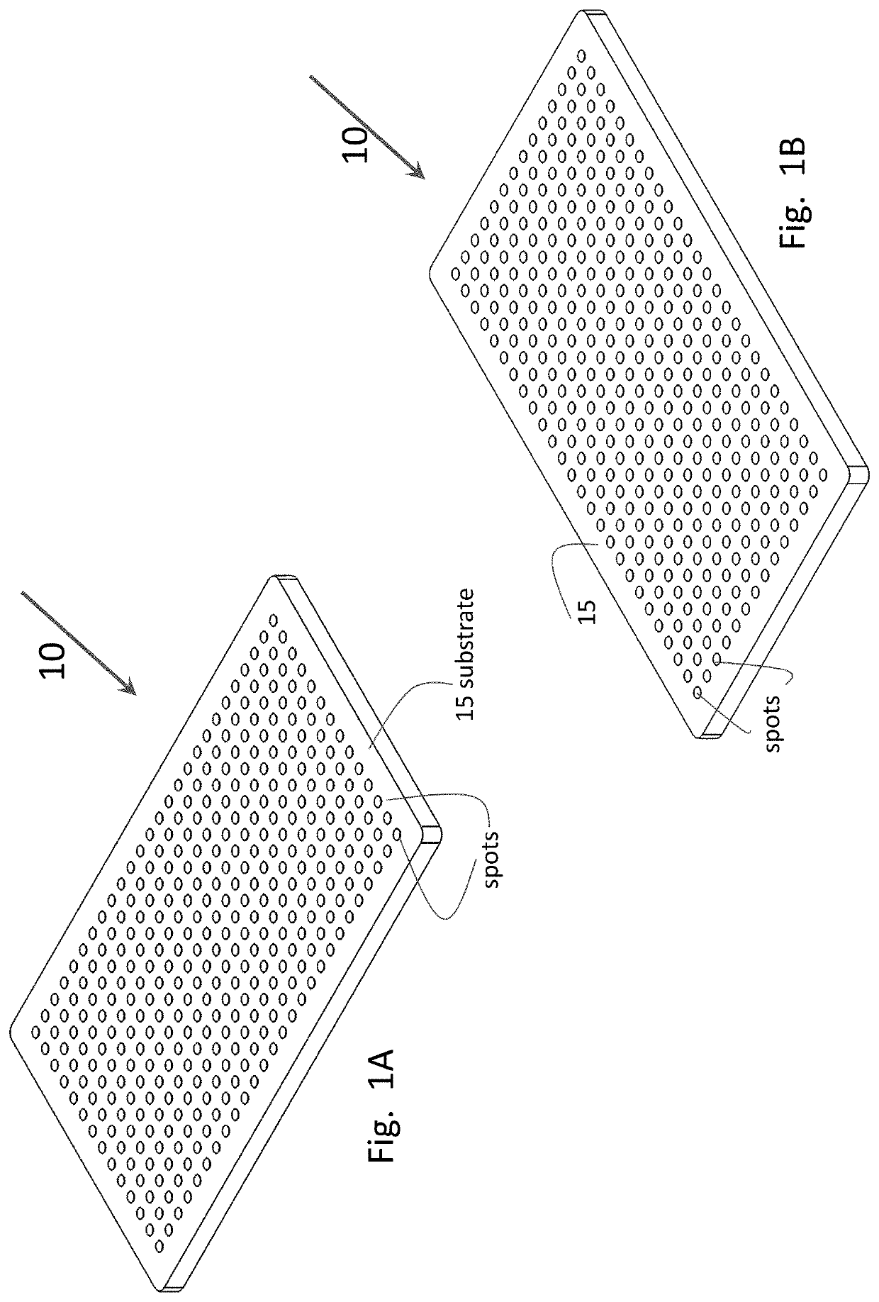
[0068]The microarray can be fabricated as described herein, although some variation can be incorporated into the fabrication procedure as known to those of skill in the art. In particular, the microarray is fabricated on 0.7 mm-thick glass substrates which are cut to dimensions of 11.0 mm in length and 6.75 mm in width. The substrates are treated with epoxysilane to create a surface to which amine-modified oligonucleotide probes can bind. (FIGS. 1A-B) The epoxysilane coating process proceeds as follows. First, the glass substrates are plasma treated with oxygen in a plasma asher (see for example, the Nordsom March plasma asher at nordson.com / en-us / divisions / march) for two minutes at 80 W power. The plasma-cleaned substrates are then immediately immersed in a freshly made solution of 2% (3-glycidyloxypropyl)trimethoxysilane in 95% ethanol and incubated for 16-18 hours at 37° C. with mixing. Following the incubation period, the substrates are removed...

example 2

dization Using the Mini Micro Array

[0072]In one example, the DNA which is hybridized to the probes on the array is fluorescently labeled with a 5′ Alexa Fluor 488 fluorophore. The DNA may be visualized on the array using a fluorescence microscope. One such example is show in FIGS. 21 A-B. As shown in the figures, there are two identical probes on the array surface and fluorescently-labeled complementary DNA is hybridized to the probes. The locations of successful hybridization are imaged using a fluorescence imaging system. Such imagining systems are well known to those of skill in the art.

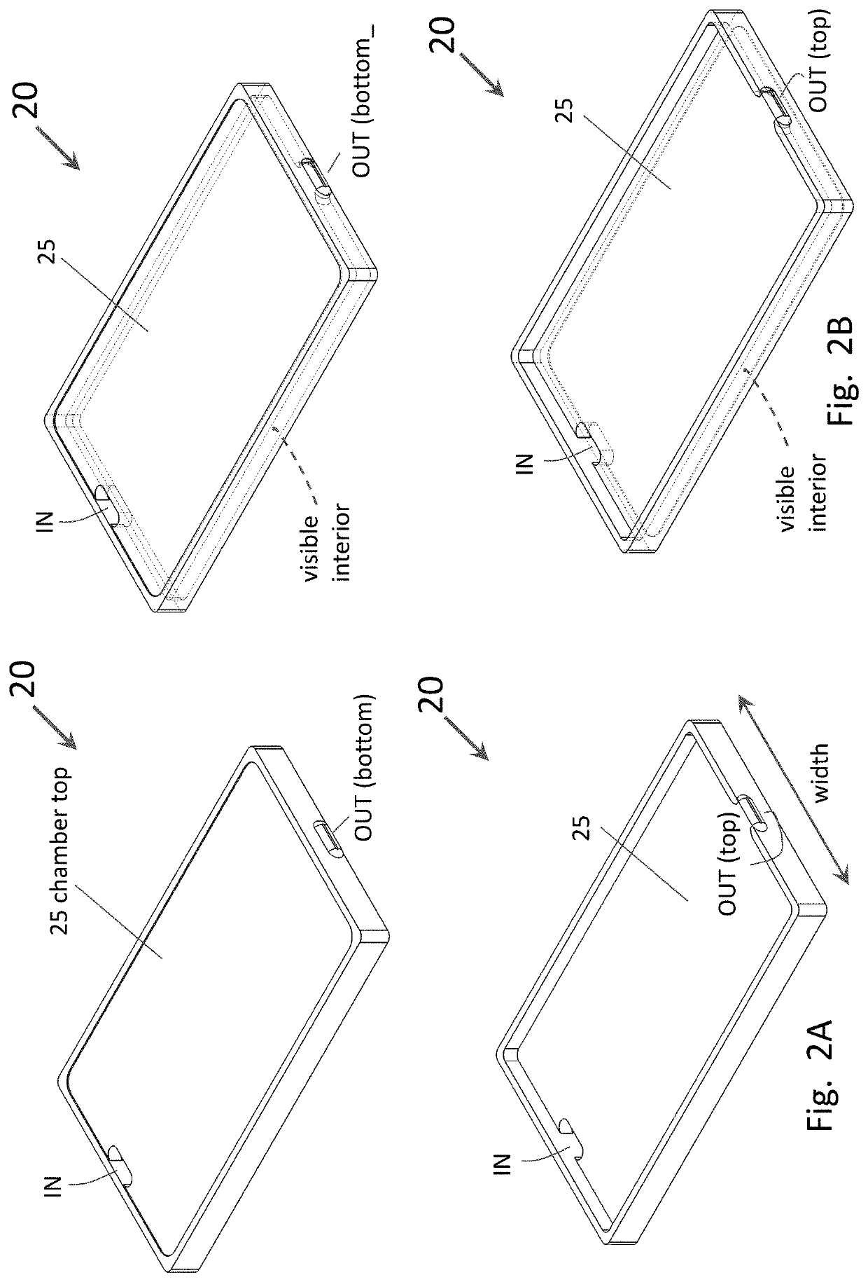
[0073]To enable ease of handling and imaging of the assembled microarrays, a custom fixture (chiplet) as shown in FIGS. 22 A-B was designed and constructed. The fixture has the same footprint as that of a 96-well plate, enabling compatibility with many standard laboratory instruments (e.g., microscopy stages). The fixture is comprised of two anodized aluminum plates and a rubber gasket. The plates...


PUM

PropertyMeasurementUnit
sizeaaaaaaaaaa
sizeaaaaaaaaaa
sizeaaaaaaaaaa

Abstract

Miniaturized DNA microarrays are described to be used in conjunction with microfluidic channels or microcentrifuge tubes and microcentrifuge filters to reduce sample size, incubation time and to increase overall binding efficiency.

Description

RELATED APPLICATIONS[0001]This application claims the benefit under 35 U.S.C. § 119(e) of U.S. Provisional Application No. 62 / 687,012, filed on Jun. 19, 2018, and U.S. Provisional Application No. 62 / 572,264, filed on Oct. 13, 2017, both of which are incorporated herein by reference in their entirety.GOVERNMENT SUPPORT[0002]This invention was made with Government support under contract number N6600118C4503, awarded by the U.S. Department of Energy. The Government has certain rights in the invention.BACKGROUND OF THE INVENTION[0003]DNA microarrays are comprised of collections of oligonucleotides, e.g., DNA, probes, which are spotted or printed in an array onto a solid support or substrate such as a glass slide. The standard size of the solid support is about the same size as a microscope slide. When these probes are exposed to a complementary target DNA in a sample, the probe and target DNA will hybridize and this hybridization reaction is generally detected optically.[0004]Some limit...

Claims


Application Information

Patent Timeline
Patent Type & Authority Applications(United States)
IPC IPC(8): B01L3/00C12Q1/6874B01L7/00C12Q1/6837B04B5/04B04B3/00
CPCB01L3/50853C12Q1/6874B01L3/502715B01L3/502746B01L7/00C12Q1/6837B01L2300/0636B04B3/00B01L2200/0689B01L2300/168B01L2300/044B01L2200/16B04B5/0414B01L2300/041B01L2300/0896
Inventor MCFARLAND, KIRSTY A.LISSANDRELLO, CHARLES A.MAGYAR, ANDREW P.ROSENBERGER, ERIN
Owner CHARLES STARK DRAPER LABORATORY
Why Eureka
Try Eureka