Glazing Assembly

a technology of glazing and assembly, applied in the direction of building components, constructions, construction materials, etc., can solve the problems of reducing the longevity of the façade, increasing the cost, and reducing the efficiency of the façade, so as to reduce the cost, reduce the cost, and improve the longevity

Inactive Publication Date: 2020-02-06
IAN RITCHIE ARCHITECTS LTD
View PDF18 Cites 0 Cited by
  • Summary
  • Abstract
  • Description
  • Claims
  • Application Information

AI Technical Summary

Benefits of technology

[0063]The non-fireable, or non-combustible, glass fibre may be held under slight compression, so as to ensure the material is not loosely packed and that it fills the entire assembly volume, so that no part of the interior volume of the assembly is unoccupied by the insulating, light diffusing material and is hung from the top of the tubular assembly.
[0064]The assembly could additionally or alternatively comprise materials having light-diffusing or scattering, or thermally or acoustically insulating properties. A number of optically translucent materials which scatter or diffuse light transmitted therethrough, and/or porous materials which trap a plurality of stationary air pockets so as to minimise heat transfer through the interior volume of the assembly are envisaged. For example, the assembly may comprise an aerogel disposed in the interior volume in order to serve this function.
[0065]Typically, an outer surface of a sheet of the assembly comprises a plurality of grooves aligned substantially parallel to the flanges of the assembly. These grooves may have a typical periodicity of the order of a millimetre or several millimetres. In use, when the assembly is disposed on the exterior of the building as a glazing panel with the grooved surface facing outwards, and the grooves aligned vertically, precipitation that is incident on the glazing may run into the grooves and downwards, owing to the force of gravity. Thereby, dirt, dust, or other materials on the exterior glazing may be carried into the grooves and downwards to the bottom of the glazing, or the façade or building overall. Thus dirt is removed from the regions of the surface between the grooves, and so this grooved surface profile may provide a self-cleaning effect by allowing the crests to remain very clean.
[0066]Thus, a self-cleaning effect may be achieved by way of a physical surface profile, without need for a hydrophobic or hydrophilic coating which previous self -cleaning solutions require. The solution of a self-cleaning surface profile has lower cost and greater longevity than such chemical-based solutions.
[0067]Typically, an outer surface of a sheet of the assembly has a

Problems solved by technology

However, these early examples failed to account for glass having virtually no dielectric property, and in such arrangements, the single outer window will quickly reach the same temperature as the outside.
However, cost starts rising dramatically.
This, coupled with access between the panes being limited, further complicates the façade construction and begins to reduce the useable floor area of the building.
But the cost of production, and the weigh

Method used


Image

  • Glazing Assembly
  • Glazing Assembly
  • Glazing Assembly

Examples


Embodiment Construction

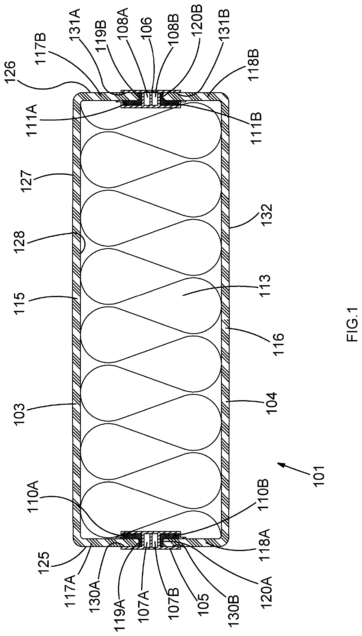
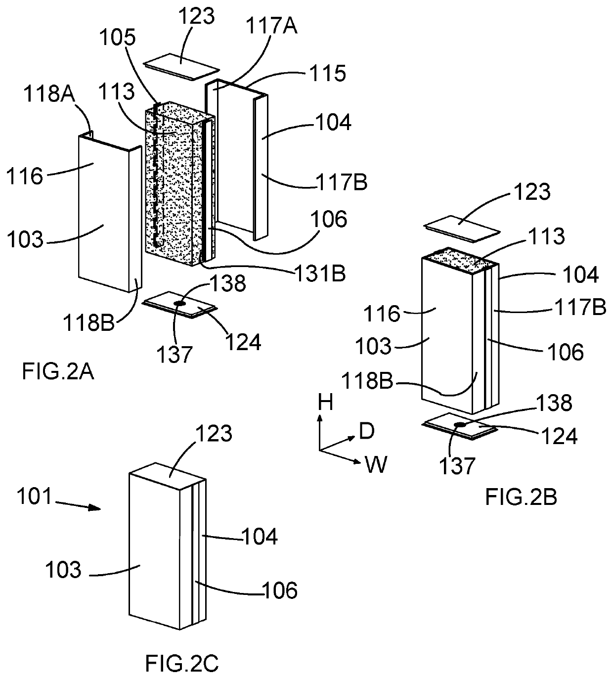
[0097]Referring to FIGS. 1 to 3, an example glazing assembly according to the invention is now described. Glazing assembly 101 comprises first and second glass U-channels 103, 104. The first U-channel member 103 comprises a planar sheet 115 with first and second perpendicular flanges 117A, 117B which project orthogonally from either side of the sheet 115 and terminate at first and second flange edges 119A, 119B, respectively. Each U-channel is made from low iron cast glass which is enamelled on the inner inside face. In the present example the project-specific width of each U-channel is 404 mm, as measured between opposite outer faces 125, 126 of first and second flanges 117A and 117B. The thickness of the glass, as measured between outer 127 and inner 128 it faces of sheet 115 is 8 mm. The glass is toughened, heat-soak tested cast glass, with enamelled frit on the inner inside face.

[0098]The tensile strength values for the toughened cast glass of the member 103 are 50 Nmm−2 for the...


PUM


Abstract

A glazing assembly is disclosed, the assembly comprising first and second toughened glass members. Each member comprises a sheet with first and second flanges projecting from opposite ends of the sheet in a direction substantially perpendicular to the sheet, and the first and second flanges of the first member are joined respectively to the first and second flanges of the second member by first and second connector portions such that the first and second flanges of the first member are substantially coplanar with the first and second flanges of the second member, respectively. A modular glazing array is also disclosed. The array comprises a plurality of glazing assemblies arranged side by side, such that at least one pair of joined, coplanar flanges of each of the plurality of glazing assemblies faces a pair of joined, coplanar flanges of another of the plurality of glazing assemblies.

Description

FIELD OF THE INVENTION[0001]The present invention relates to a glazing assembly comprising first and second toughened glass members. In particular, the invention relates to an assembly wherein first and second toughened glass members are joined together such that the structural performance of the assembly is improved.[0002]BACKGROUND TO THE INVENTION[0003]U-channel cast glass is a low-cost cladding material which has been available on the market for over four decades. These U-channels comprise a strip of glass bent or moulded in a U-shape, typically using a machine rolling process, and generally come in a set number of profiles and widths which are broadly homogenous across manufacturers worldwide. Widths available are generally circa 232 mm, 262 mm and 330 mm. As a general principle, the wider the U-channel, that is the greater the distance across the central sheet or between the return flanges, the less vertical distance it can span. Furthermore, wider U-channels generally require...

Claims


Application Information

Patent Timeline
IPC IPC(8): E04C2/54E04C1/42
CPCE04C2/54E04C1/42
Inventor RITCHIE, IAN
Owner IAN RITCHIE ARCHITECTS LTD
Why Eureka
Try Eureka