Statically stable robot using wheel with inner system

a technology of static stability and robots, applied in the direction of electric propulsion mounting, light to electrical conversion, battery/cell propulsion, etc., can solve the problems of obstructing space, rendering known vehicles of this type unsuitable for applications requiring relatively high ground clearance, and reducing ground clearan

Active Publication Date: 2018-01-25
AGERRIS PTY LTD
View PDF4 Cites 23 Cited by
  • Summary
  • Abstract
  • Description
  • Claims
  • Application Information

AI Technical Summary

Benefits of technology

[0029]Thus, the vehicle may be interoperable as a trailer, rather than a prime mover, whereby the prime mover (e.g. tractor, truck, etc.) can tow the vehicle without any requirement for the vehicle to localise and path plan its own position and course. In some embodiments, the may be adapted to generate electricity for its payload or to charge its batteries as it moves, whereby the operator does not need to connect electronic or other systems to power the vehicle when it is being used as a trailer. In such embodiments, the vehicle advantageously uses kinetic energy sourced from the leading vehicle through its wheels.

Problems solved by technology

However, due to the absence of a third wheel, stability is an inherent challenge both statically and dynamically.
However, this inherently obstructs the space between the wheels and compromises ground clearance, thus rendering known vehicles of this type unsuitable in applications requiring relatively high levels of ground clearance.
Moreover, the heavier the payload needed to be carried, and the higher centre of gravity of the payload, the lower the centre of gravity of the chassis structure must be, and hence the more the ground clearance must be reduced.
However, this inevitably gives rise to other design compromises in terms of overall vehicle size, weight, manoeuvrability and / or cost of manufacture.

Method used


Image

  • Statically stable robot using wheel with inner system
  • Statically stable robot using wheel with inner system
  • Statically stable robot using wheel with inner system

Examples


Embodiment Construction

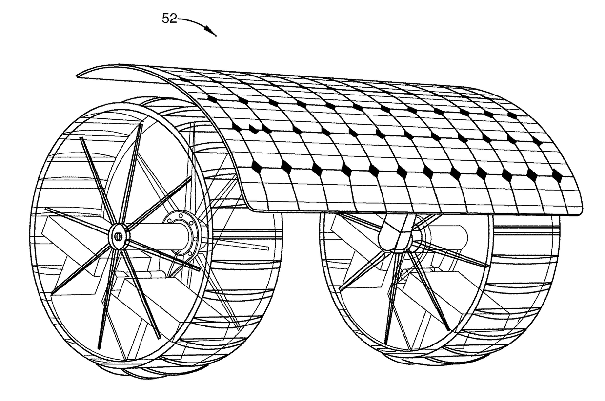
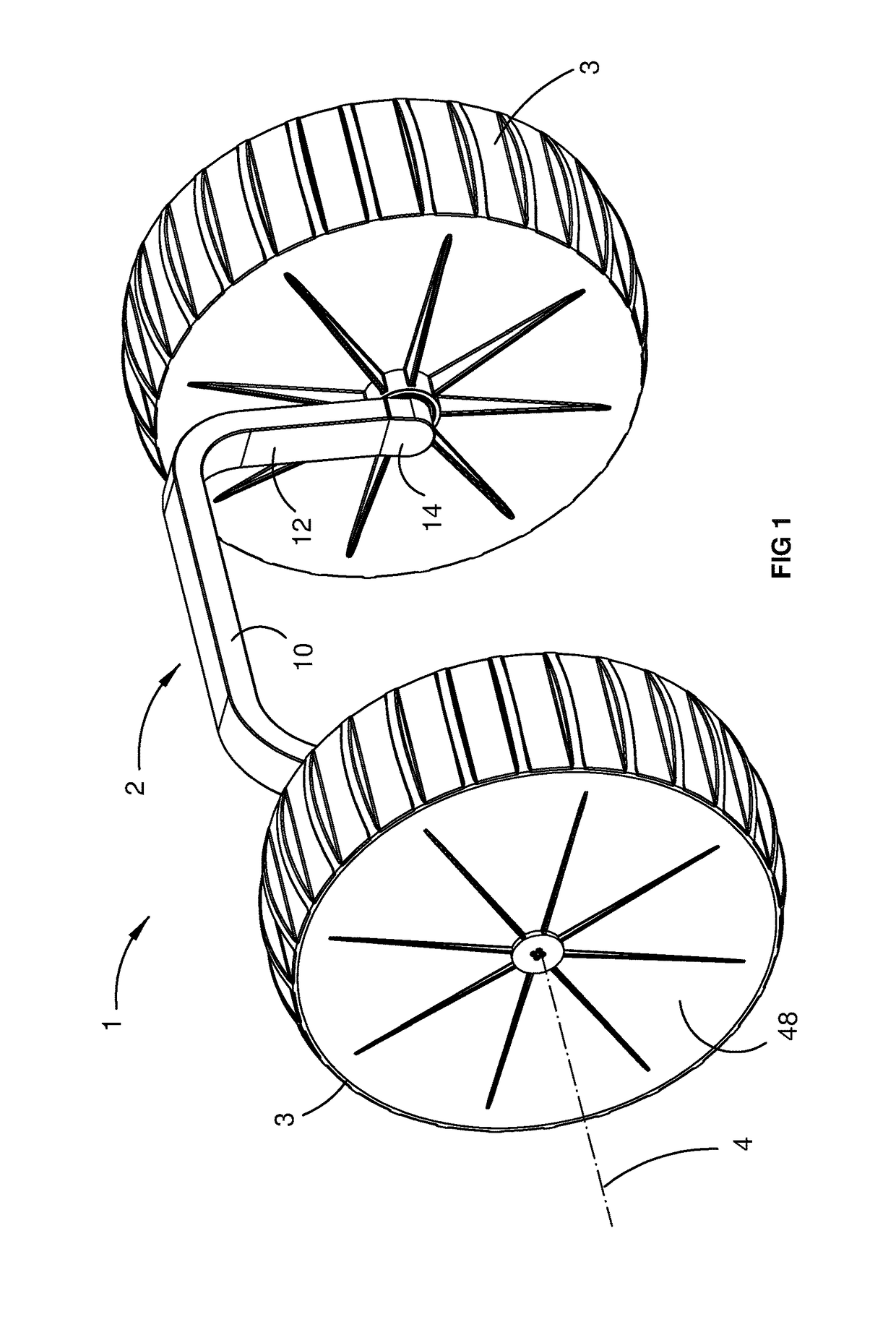
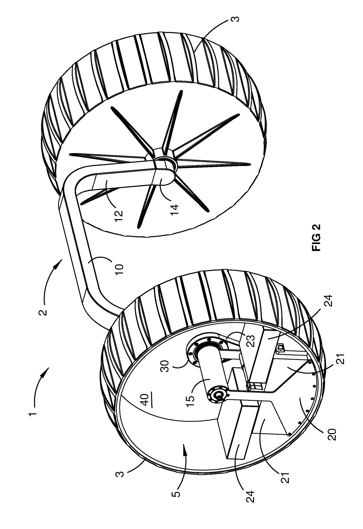
[0041]Referring initially to FIGS. 1 to 3, the invention provides an omni-directional di-wheel vehicle 1 including a chassis 2, a pair of wheels 3 supported in spaced apart relationship by the chassis for rotation about a common axis 4, and a pair of drive modules 5 associated with the respective wheels. The wheels may incorporate integral treads or tyres as required for the intended application.

[0042]The chassis 2 includes a transverse bridge section 10, and a pair of legs 12 extending generally downwardly from opposite sides of the bridge section. The legs 12 are connected at their lower ends to the respective drive modules 5 by means of lugs 14 and tubular axle formations 15, which in turn support the respective wheels for independent rotation about the common axis, as described more fully below. The drive modules 5 and the chassis 2 are thereby interconnected via the tubular axle formations as a discrete subassembly 16 for rotation relative to the wheels about the common axis 4....


PUM


Abstract

The invention relates to a vehicle including a chassis and a pair of wheels supported in spaced apart relationship by the chassis for rotation about a common axis. A pair of drive modules is associated with the respective wheels. The drive modules and the chassis are connected for rotation as a sub-assembly relative to the wheels about the common axis with the centre of mass of the sub-assembly below the common axis in a static equilibrium position. Each of the drive modules is housed substantially within the respective wheel.

Description

FIELD OF THE INVENTION[0001]The present invention relates generally to di-wheel vehicles. The Invention has been developed more particularly for use as a mobile platform in robotic applications such as in connection with agricultural, mining, defence, education, research, medical practice, space, logistics, urban and domestic robots and will be described predominately in this context. It should be appreciated, however, that the invention is not limited to this field of use, being potentially applicable in a wide variety of applications where a highly manoeuvrable vehicle or mobile platform is advantageous, including in the field of personal transportation.BACKGROUND OF THE INVENTION[0002]The following discussion of the prior art is intended to place the invention in an appropriate technical context and enable its advantages to be more fully appreciated. However, any references to prior art throughout this specification should not be construed as an express or implied admission that ...

Claims


Application Information

Patent Timeline
Patent Type & Authority Applications(United States)
IPC IPC(8): B60K7/00B60K1/04B60K17/04B60L8/00
CPCB60K7/0007B60L8/003B60K1/04B60K17/043B60L11/1877B60L11/1879B60K2001/045B60K2007/0038B60K2007/0061B60L2200/16B60K7/0015B60K7/0023B60L50/66B60L50/64Y02T10/7072A01G25/09
Inventor CALLEIJA, MARKSUKKARIEH, SALAH
Owner AGERRIS PTY LTD
Why Eureka
Try Eureka