Dropping mechanism with universal mounting points

a technology of mounting points and dropping mechanisms, which is applied in the field of camera-actuated mechanical release devices, can solve the problems of difficult or user-friendly access to drones, scarce drone control units with additional connection ports for accessories, and the majority of drones cannot attach a dropping system withou

Inactive Publication Date: 2018-01-25
MCCASLIN DUSTIN
View PDF2 Cites 13 Cited by
  • Summary
  • Abstract
  • Description
  • Claims
  • Application Information

AI Technical Summary

Benefits of technology

[0017]The release trigger has a flat shoe that comes into contact with the drone's camera, a release trigger notch and a release trigger mounting hole. The release trigger notch fits into the retention groove and keeps the retaining pin in place until the payload needs to be released. To release the payload, the camera of the drone is directed straight down causing it to come into contact with the flat shoe of the release trigger. This force imparted on the flat shoe lifts the release trigger notch out of a retention groove, allowing the elastic strap to pull the sliding restraint from the secured position to the drop position.
[0018]The mechanism housing keeps the release trigger and sliding restraint in place by pressing them against the base plate. The mechanism housing mounts to the base plate with mounting retaining clips. The mechanism also contains a pin that protrudes through the release trigger and acts as a fulcrum when the release trigger is pushed by the drone's camera. The mechanism housing also has a mechanism housing aperture that is similar in size to the base plate aperture. The mechanism housing is connected to the base plate such that the mechanism housing aperture is approximately aligned with the base plate aperture. The inclusion of a mechanism housing aperture ensures sufficient clearance for the payload hook or payload strap placed around the retaining pin of the sliding restraint when in the secured position.
[0019]In use, a user first connect

Problems solved by technology

Currently, accessorizing a drone is not easy or user friendly.
Other than the connection port for the battery and camera, additional connection ports to the drone control unit for accessories are scarce.
However, most drones cannot attach a dropping system without removing the camera.
Not watching the dropped object, can result in a poorly dropped payload, since the user cannot view the intended drop area.
Also, gently placing fragile packages down becomes almost impossible.
By removing the perspective of the drone, t

Method used


Image

  • Dropping mechanism with universal mounting points
  • Dropping mechanism with universal mounting points
  • Dropping mechanism with universal mounting points

Examples


Embodiment Construction

[0046]The Dropping Mechanism with Universal Mounting Points is capable of being mounted to a drone, allowing the user to carry and drop a payload, as well as attach additional accessories in multiple orientations.

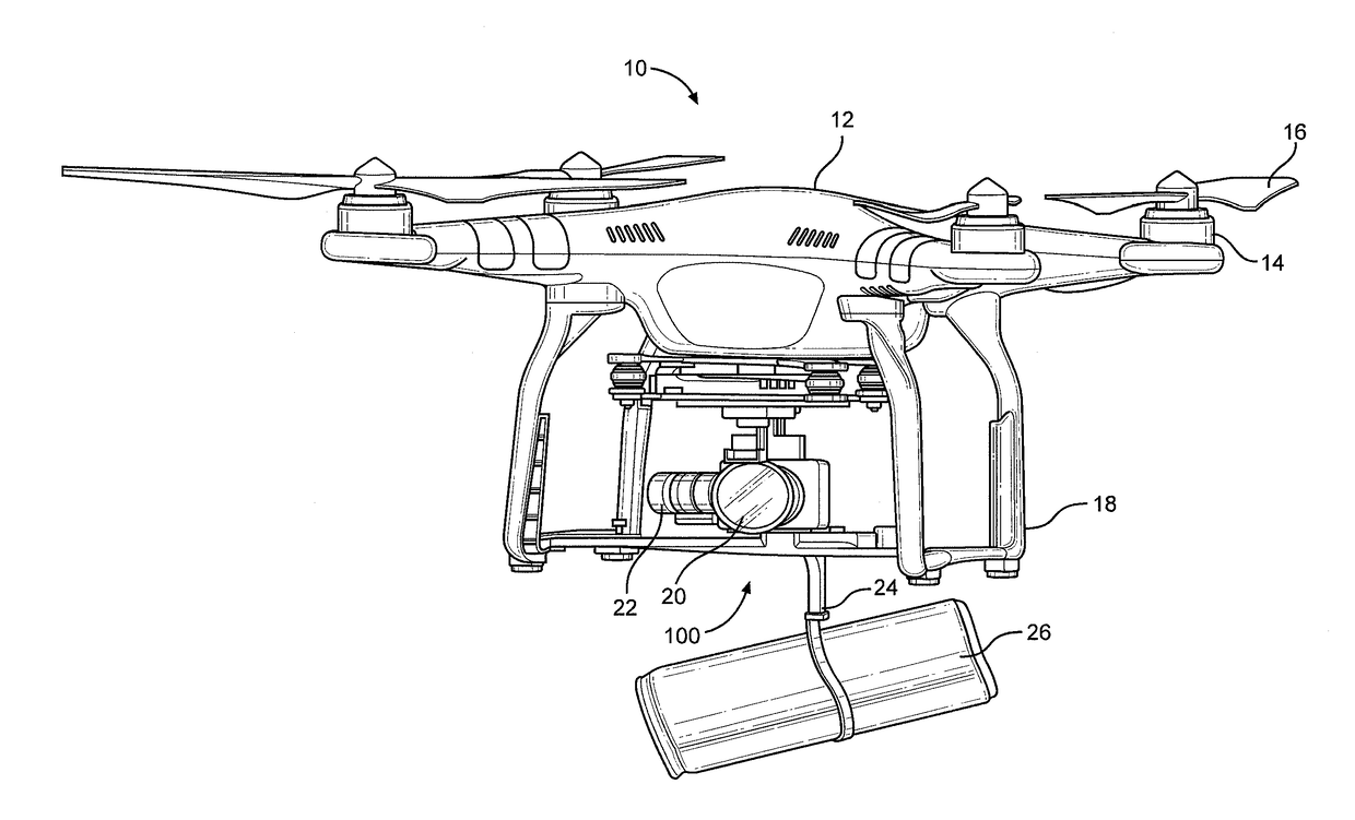
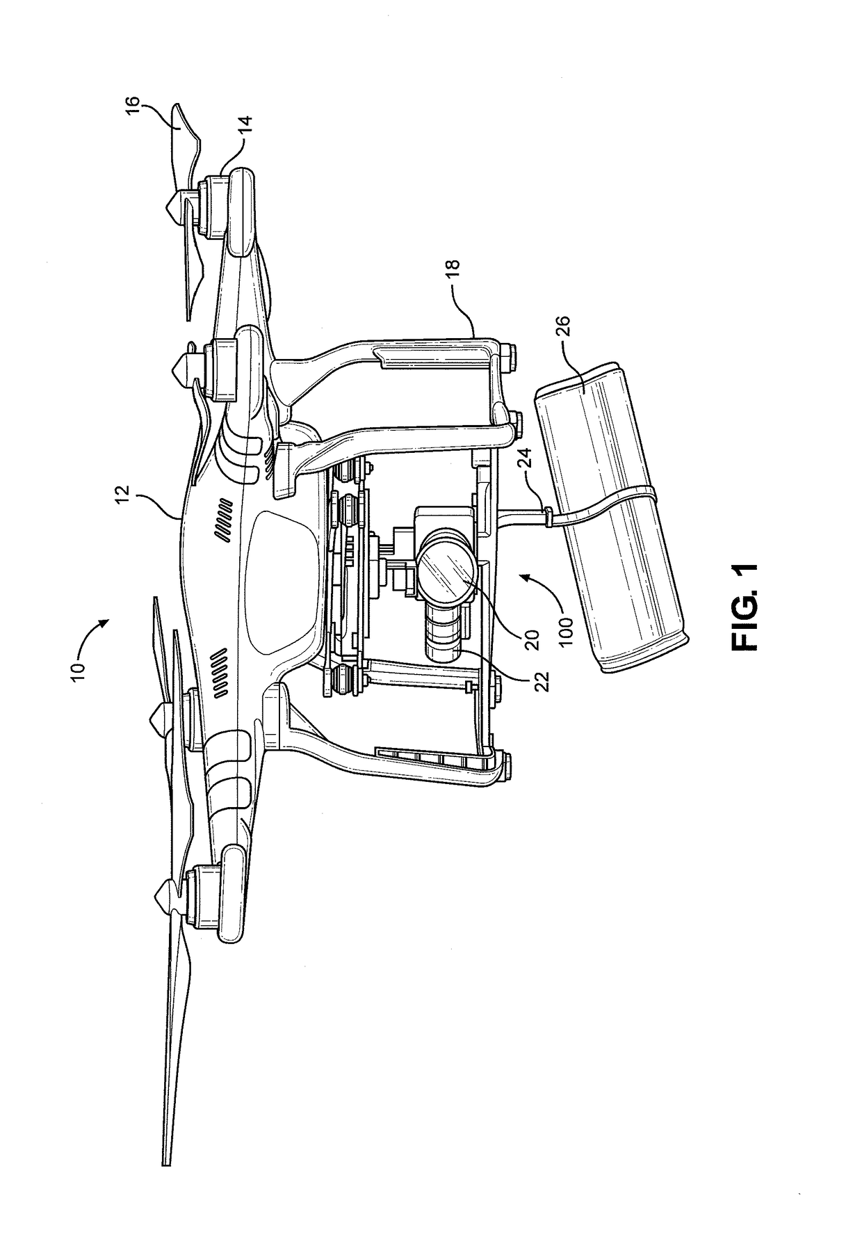
[0047]Referring initially to FIG. 1, the present invention is shown and generally designated 100. As depicted in FIG. 1, the Dropping Mechanism 100 of the present invention is attached to a drone 10 at the drone landing gear 18 of the drone 10 and is shown carrying a payload 26 fastened to the Dropping Mechanism 100 by a payload hook 24.

[0048]The drone 10 has a drone control unit 12 that receives radio frequency signals from a transmitter to power the flight motors 14, camera 20 and camera motor 22. The Dropping Mechanism 100 holds payload 26 as flight motors 14 propel rotating propellers 16, which in turn provide lift and thrust to the drone 10. The camera 20 is adjusted with camera motors 22 to enable a user to film and view the flight from the perspective of the drone 10...


PUM


Abstract

A dropping mechanism with universal mounting points includes a device for securing a payload to a drone, mechanically releasing it and mounting additional accessories that can be used during flight. The dropping mechanism can be attached to either the landing gear or body of the drone, in an orientation that allows contact between the release trigger and the drone's camera. A notch and groove system holds a sliding restraint in place, keeping the payload secure during flight. Once the release trigger is pushed, an energized member pulls the sliding restraint allowing the payload to drop. Since the camera is pointed down to actuate the trigger, the user can watch as the payload falls to the ground. The use of a mechanical dropping system makes this device compatible with drones that only have an electrical connection for the camera. Universal mounting points allow attachment of a wide variety of accessories.

Description

RELATED APPLICATION[0001]This application claims the benefit of priority to the United States Provisional Patent Application for “DROPPING MECHANISM WITH UNIVERSAL MOUNTING POINTS”, Application No. 62 / 364,651 filed on Jul. 20, 2016.FIELD OF THE INVENTION[0002]The present invention pertains generally to a camera actuated mechanical release device used in conjunction with remote controlled drones. More specifically, the present invention pertains to a latching device capable of being attached to a drone that allows the user to carry a payload and by moving the camera to a pre-determined position, drop the carried payload. The present invention is particularly, but not exclusively, useful as a convenient way to carry objects with a drone, fly them to a desired location, and release them when they are over the intended drop zone. The base plate for the dropping device can be configured to attach to the landing gear of different drones and configured to carry payloads of different weight...

Claims


Application Information

Patent Timeline
IPC IPC(8): B64D1/12B64C39/02B64D47/08
CPCB64D1/12B64D47/08B64C39/024B64C2201/126B64C2201/165B64C2201/146B64C2201/027B64C2201/108B64C2201/128B64U10/13B64U2201/20B64U60/00B64U2101/64B64U30/20B64U50/13B64U2101/00B64U2101/60
Inventor MCCASLIN, DUSTIN
Owner MCCASLIN DUSTIN
Why Eureka
Try Eureka