
Electromagnetic-released, multi-disc enclosed safety brake
a safety brake and electromagnetic release technology, applied in the direction of passenger handling apparatus, transportation and packaging, hoisting equipment, etc., can solve the problems of increasing the centripetal force, reducing the allowable speed, increasing the diameter and number of friction interfaces,
- Summary
- Abstract
- Description
- Claims
- Application Information
AI Technical Summary
Benefits of technology
Problems solved by technology
Method used
Image

Examples
Embodiment Construction
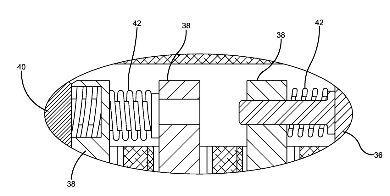
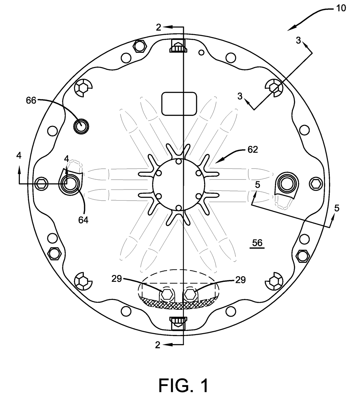
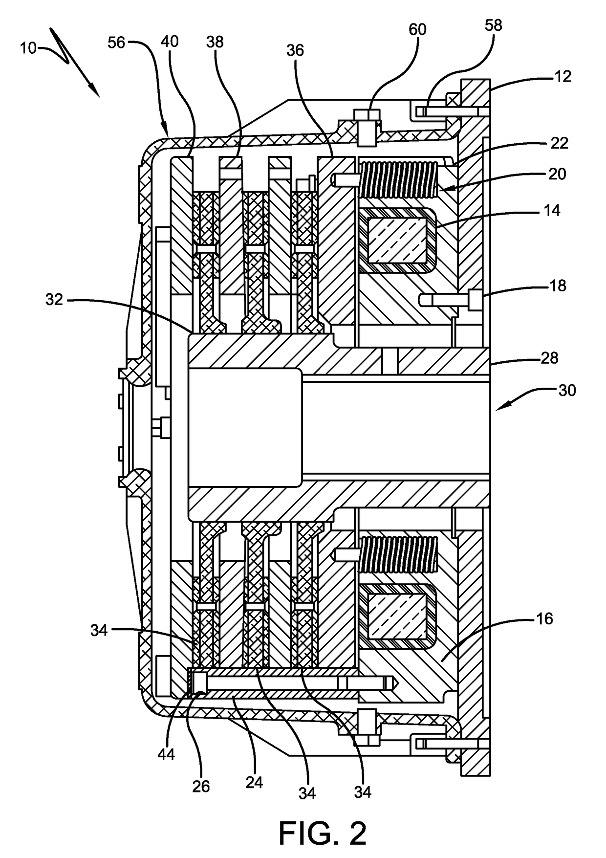
[0035]Referring now to the drawings, and more particularly FIGS. 1 and 2, it can be seen that the motor brake assembly according to the invention is designated generally by the numeral 10. A mounting plate 12 is adapted to mount a motor flange (not shown) and is positioned by means of a pilot interface. An electromagnetic coil assembly 14 is maintained by a housing 16, which is secured to the mounting plate 12 by appropriate screws 18. The coil assembly 14 is comprised of a wound copper coil and electrically-isolating potting. The coil housing 16 includes cylindrical pockets 20 containing apply springs 22 that are uniformly circumferentially spaced within the housing 16. The torque blocks 24, as shown in FIG. 2, are secured to the coil housing using threaded fasteners 26 and located by means of appropriate alignment bushings. There are preferably three torque blocks 24, each rectangular in cross-section and circumferentially spaced 120° apart. Torque blocks have been found to be mor...
PUM
 Abstract
Description
Claims
Application Information