Method and apparatus for an imaging system of biological material

Active Publication Date: 2018-01-25
FLITSCH FREDERICK A
View PDF9 Cites 6 Cited by
  • Summary
  • Abstract
  • Description
  • Claims
  • Application Information

AI Technical Summary

Benefits of technology

[0015]In some embodiments, the methods of producing products in the mentioned cleanspace fabricator may be useful to produce small amounts of a product. An imaging system comprised of a multitude of individual imaging elements may define a lithography option for a low volu

Problems solved by technology

The use of the tool chassis together with a toolPod may res

Method used


Image

  • Method and apparatus for an imaging system of biological material
  • Method and apparatus for an imaging system of biological material
  • Method and apparatus for an imaging system of biological material

Examples


Embodiment Construction

[0058]In patent disclosures by the same inventive entity, the innovation of the cleanspace fabricator has been described. In place of a cleanroom, fabricators of this type may be constructed with a cleanspace that contains the wafers, typically in containers, and the automation to move the wafers and containers around between ports of tools. The cleanspace may typically be much smaller than the space a typical cleanroom may occupy and may also be envisioned as being turned on its side. In some embodiments, the processing tools may be shrunk which changes the processing environment further.

Description of a Linear, Vertical Cleanspace Fabricator

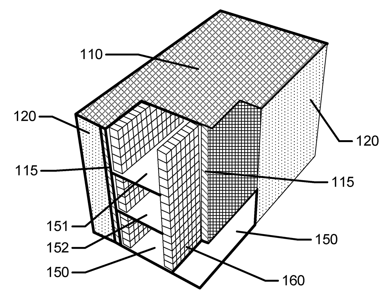
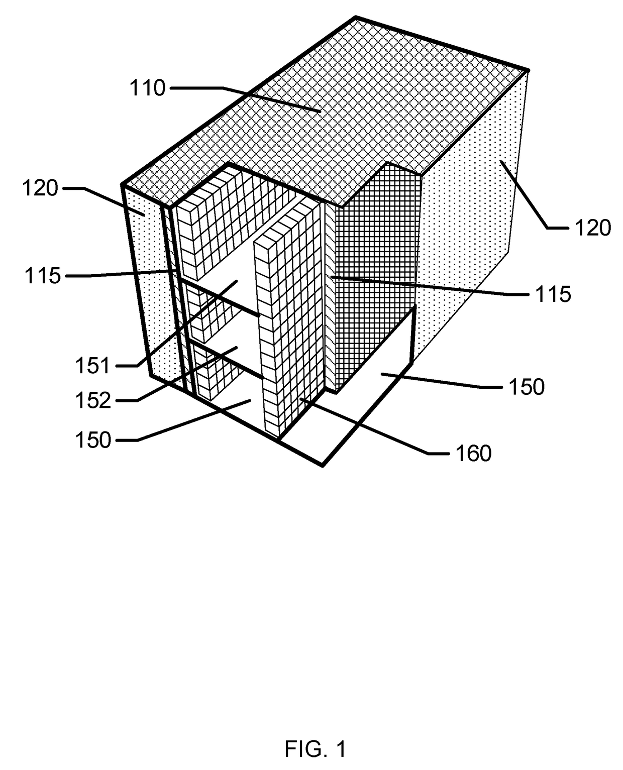
[0059]There are a number of types of cleanspace fabricators that may be possible with different orientations. For the purposes of illustration, one exemplary embodiment includes an implementation with a fab shape that is planar with tools oriented in vertical orientations. An exemplary representation of what the internal structure of these type...


PUM

PropertyMeasurementUnit
Sizeaaaaaaaaaa
Pressureaaaaaaaaaa
Distanceaaaaaaaaaa

Abstract

The present invention provides apparatus for an imaging system comprising a multitude of chemical emitting elements upon a substrate. In some embodiments the substrate may be approximately round with a radius of approximately one inch. Various methods relating to using and producing an imaging system of chemical emitters are disclosed.

Description

CROSS REFERENCE TO RELATED APPLICATIONS[0001]This application is a continuation in part of the Utility application Ser. No. 14 / 861,737, filed Sep. 22, 2015 and entitled: “METHOD AND APPARATUS FOR AN ELECTROMAGNETIC EMISSION BASED IMAGING SYSTEM.” The application Ser. No. 14 / 861,737 in turn is a continuation in part of the Utility application Ser. No. 14 / 861,737, filed Sep. 22, 2015 and entitled: “METHOD AND APPARATUS FOR A HIGH RESOLUTION IMAGING SYSTEM.” The application Ser. No. 14 / 861,737 in turn is a continuation in part of the Utility application Ser. No. 14 / 594,335, filed Jan. 12, 2015 and entitled: “METHOD AND APPARATUS FOR AN IMAGING SYSTEM.” The application Ser. No. 14 / 594,335 in turn claims the benefit of the United States Provisional Application bearing the Ser. No. 61 / 926,471, filed Jan. 13, 2014 and entitled METHOD AND APPARATUS FOR AN IMAGING SYSTEM. The contents of each are relied upon and hereby incorporated by reference.FIELD OF THE INVENTION[0002]The present inventi...

Claims


Application Information

Patent Timeline
IPC IPC(8): H01J37/06H01J9/02H01J37/20H01J37/244H01J37/317H01J37/08
CPCH01J37/06H01J37/317H01J37/08H01J37/20H01J37/244H01J37/3177H01J9/022G03F7/0002G03F9/00H01J2237/1205H01J2237/303H01J2237/304H01J2237/31759H01J2237/31798H01J37/248H01J2237/20H01J2237/3174Y10T29/49004B33Y10/00
Inventor FLITSCH, FREDERICK A.
Owner FLITSCH FREDERICK A
Why Eureka
Try Eureka