Electric power storage apparatus

a technology of electric power storage and storage apparatus, which is applied in the direction of battery/fuel cell control arrangement, safety/protection circuit, pulse technique, etc., can solve the problems of electric shock to the occupant or the like, the insulation resistance between the high-voltage circuit and the ground may be lowered, etc., and achieve the effect of effective use of storage power

Inactive Publication Date: 2018-01-25
YAZAKI CORP
View PDF2 Cites 4 Cited by
  • Summary
  • Abstract
  • Description
  • Claims
  • Application Information

AI Technical Summary

Benefits of technology

[0029]According to the electric power storage apparatus having the configuration of (5) above, the operating state of the battery circuit can be detected by using the detection circuit. Moreover, the electric source power which is necessary to drive the detection circuit can be generated based on the power stored in the power storage element, and therefore the stored power can be effectively used.
[0030]According to the invention, it is possible to provide an electric power storage apparatus in which it is not required to, in order to control the operation of the apparatus itself, supply a power source power from a low-voltage circuit, and therefore the low-voltage circuit can be isolated from a high-voltage circuit in the vicinity of a main battery.

Problems solved by technology

However, there is a possibility that the insulation resistance between the high-voltage circuit and the ground may be lowered due to deterioration, a failure, a change in the environment such as the humidity, a collision of the vehicle, or the like.
When the insulation resistance is lowered, there arises a possibility that the occupant or the like may receive an electric shock.
However, the mixed existence of low- and high-voltage circuits is not preferable because of the difference in their voltages, and hence it is desired to isolate a high-voltage circuit and a low-voltage circuit from each other.

Method used


Image

  • Electric power storage apparatus
  • Electric power storage apparatus
  • Electric power storage apparatus

Examples


Embodiment Construction

[0036]Hereinafter, a specific embodiment of the invention will be described with reference to the drawings.

[0037]Firstly, the configuration and operation of the entire embodiment will be summarized.

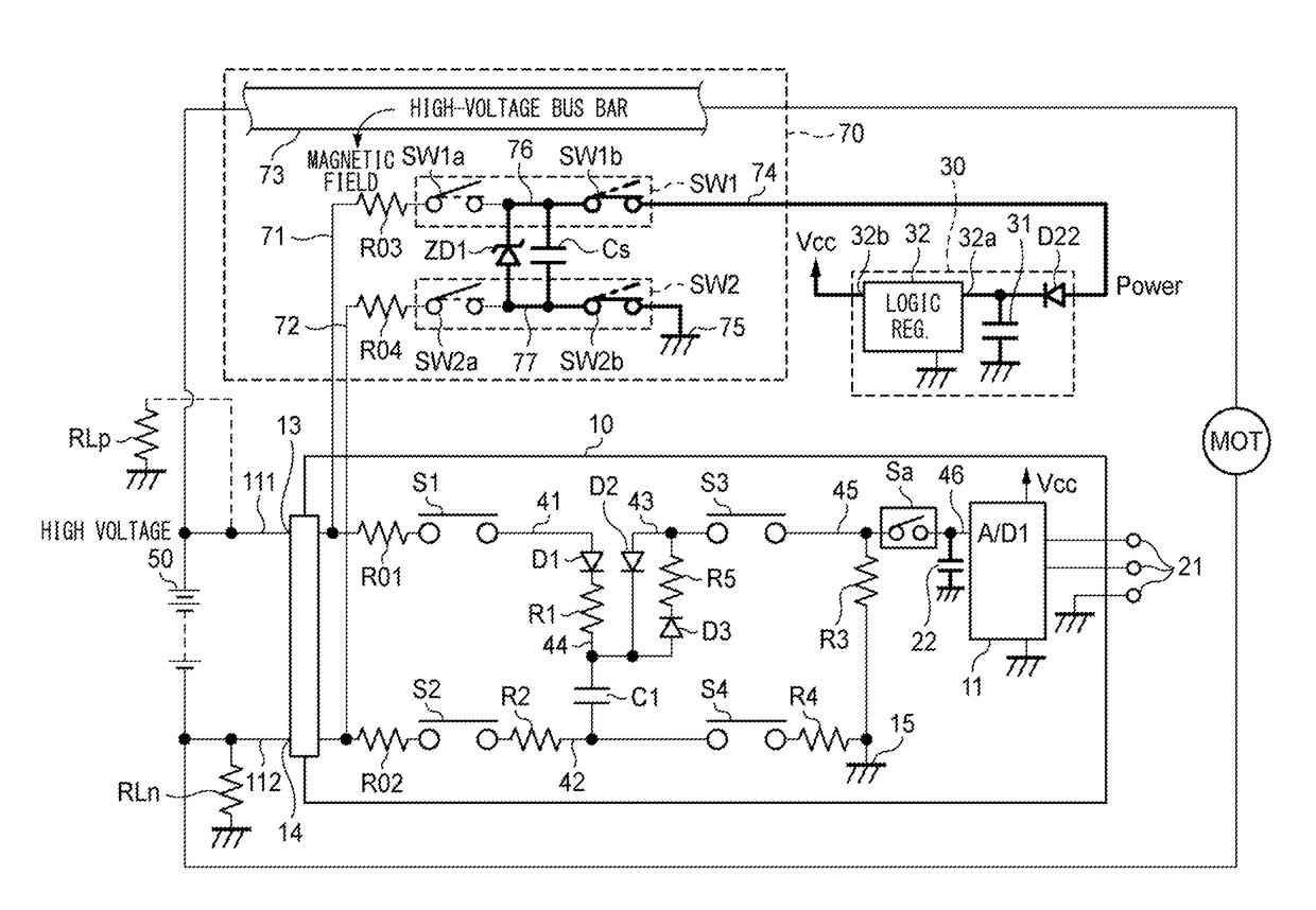
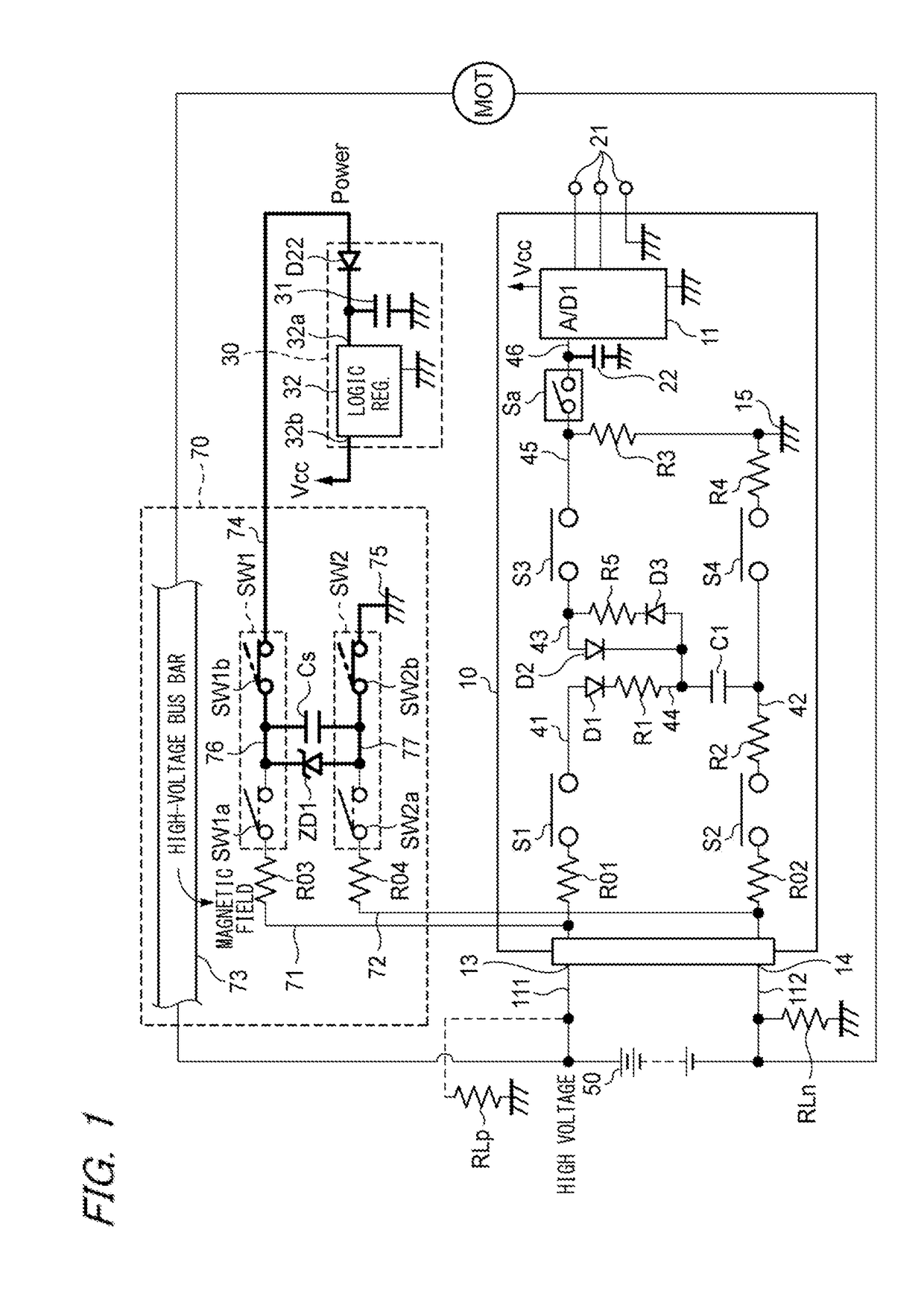
[0038]FIG. 1 shows main components of a system including an electric power storage apparatus of the embodiment of the invention. The system shown in FIG. 1 includes a ground fault measurement circuit (detection circuit) 10 which is used for detecting the ground fault resistance on a vehicle, and peripheral circuits which generate an electric source power that is necessary for on-vehicle apparatuses such as the ground fault measurement circuit 10 to operate. The peripheral circuits include the electric power storage apparatus 70.

[0039]In the example shown in FIG. 1, it is assumed that the electric power storage apparatus 70 is used for generating an electric source power which is necessary for the ground fault measurement circuit 10 to measure the ground fault resistance. Alternatively, th...


PUM


Abstract

A power storage device which receives an electric power from a high-voltage circuit of a vehicle is disposed, and reed switches are disposed in a circuit which switches a connection state of the power storage device. In the reed switches, the ON/OFF state is switched depending on the energization/deenergization and energization direction of a high-voltage bus bar which is placed at a proximal position. Moreover, a permanent magnet which generates a DC magnetic field to apply a bias in a specific direction is placed in the vicinity of the reed switches, and switching according to the energization direction is enabled. A movable permanent magnet is placed in the vicinity of the high-voltage bus bar, and the position of the permanent magnet is changed depending on the energization/deenergization and the energization direction.

Description

CROSS REFERENCE TO RELATED APPLICATIONS[0001]This application is based on and claims priority from Japanese patent application No. 2016-142556 filed on Jul. 20, 2016, the entire contents of which are incorporated herein by reference.BACKGROUND OF THE INVENTION1. Technical Field[0002]The present invention relates to an electric power storage apparatus including a power storage element which can store an electric power supplied from a battery circuit of a vehicle.2. Background Art[0003]In a vehicle such as a hybrid vehicle including an internal combustion engine and an electric motor as a driving source for generating a propulsion force, or an electric vehicle, a high-voltage main battery or the like mounted on the vehicle body is charged, and the propulsive force is generated by using electric energy supplied from the main battery or the like. A power source circuit which generates electric energy for producing a propulsive force for the vehicle, and which is configured by the main b...

Claims


Application Information

Patent Timeline
Patent Type & Authority Applications(United States)
IPC IPC(8): H02J7/00H03K17/97
CPCH02J7/0031H03K17/97H02J7/0036B60L3/0069H02J7/0029B60L2210/12B60L58/10H01H36/008Y02T10/72Y02T10/70H02J7/00308
Inventor KAWAMURA, YOSHIHIRO
Owner YAZAKI CORP
Why Eureka
Try Eureka