Electric driving apparatus
- Summary
- Abstract
- Description
- Claims
- Application Information
AI Technical Summary
Benefits of technology
Problems solved by technology
Method used
Image
Examples
first embodiment
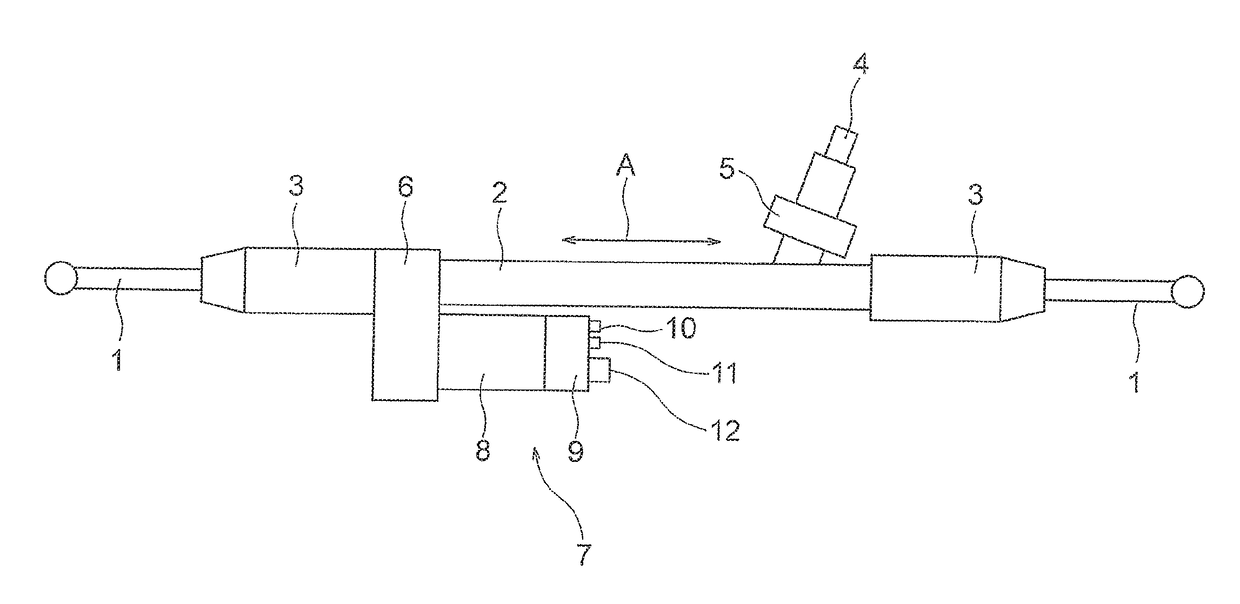
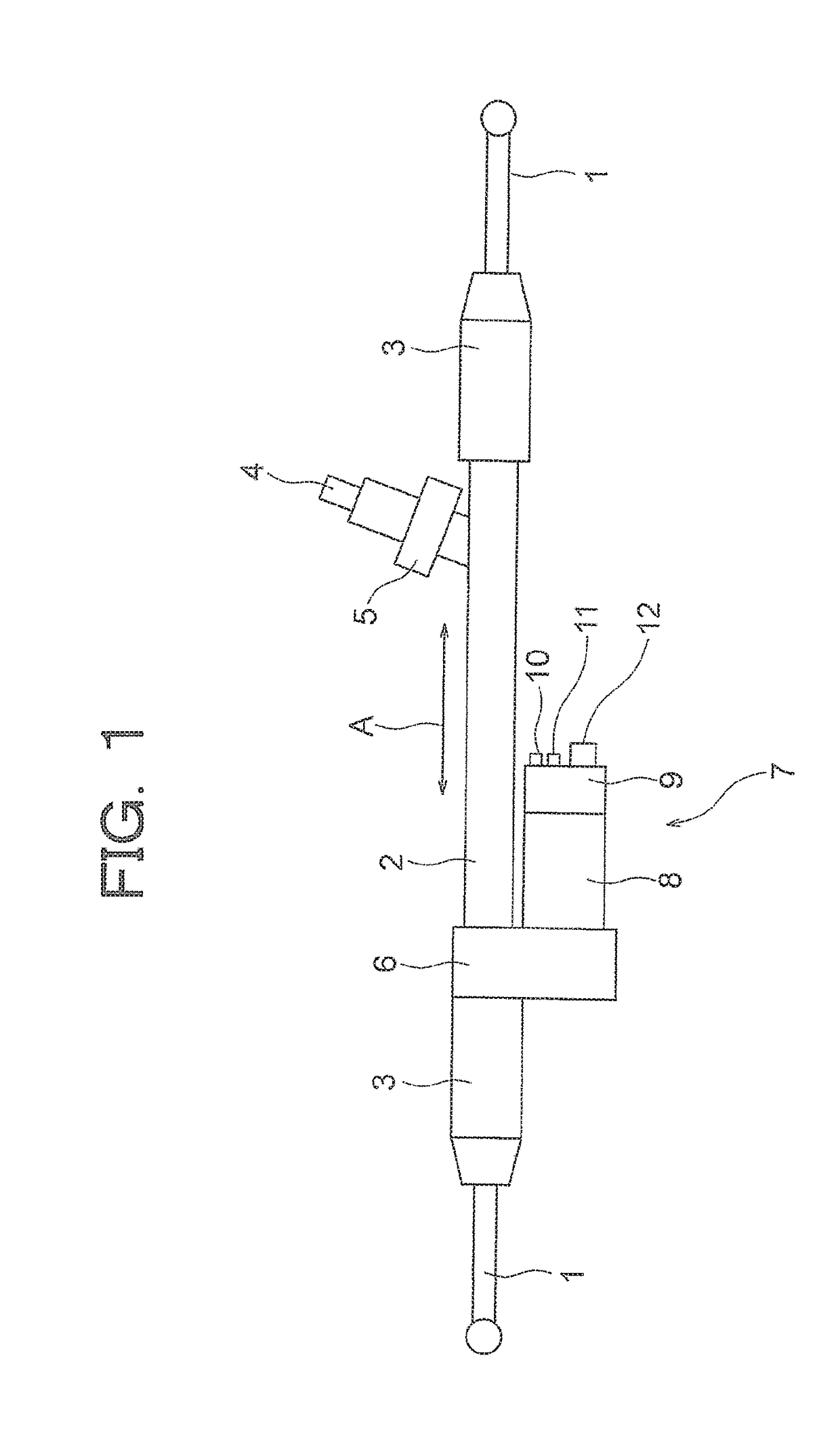
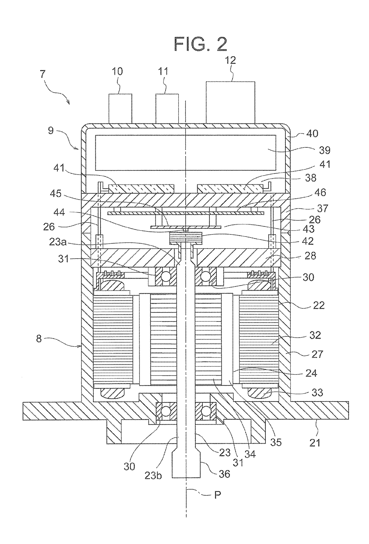
[0030]FIG. 1 is a view showing a configuration of an electric power steering apparatus according to a first embodiment of this invention. The electric power steering apparatus according to this embodiment is an electric power steering apparatus for a vehicle, which is installed in a vehicle such as an automobile, for example. A rack shaft (not shown) housed in a housing 2 is connected between a pair of tie rods 1. Respective connection portions between the tie rods 1 and the rack shaft are housed in rack boots 3 that prevent foreign matter from infiltrating the electric power steering apparatus. A shaft 4 is connected to the rack shaft. When a driver turns a steering wheel (not shown), steering torque generated as a result is transmitted to the rack shaft via a steering shaft (not shown) and the shaft 4. A torque sensor 5 for detecting the torque generated by turning the steering wheel is provided on the shaft 4. Further, an electric driving apparatus 7 is provided on the rack shaft...
second embodiment
[0087]In the first embodiment, the respective current phase differences between the feeder wires 26 are set at 0° between the U1 phase and the U2 phase, between the V1 phase and the V2 phase, and between the W1 phase and the W2 phase, but instead, the respective current phase differences between the feeder wires 26 may be set at 30° between the U1 phase and the U2 phase, between the V1 phase and the V2 phase, and between the W1 phase and the W2 phase. In other words, in this embodiment, the current phases of the respective feeder wires 26 are set to differ by 30° between the U1 phase and the U2 phase, between the V1 phase and the V2 phase, and between the W1 phase and the W2 phase. All other configurations are identical to the first embodiment.
[0088]Next, the effect exerted on the rotation sensor 44 by the magnetic fields from the respective feeder wires 26 in this embodiment when the rotation sensor 44 and the respective feeder wires 26 have the positional relationship shown in FIG...
third embodiment
[0095]In the first embodiment, a current flows through each of the feeder wires 26, but some of the currents flowing through the respective feeder wires 26 may be permanently stopped. In this embodiment, of the currents flowing through the feeder wires 26 of the U1 phase, the V1 phase, the W1 phase, the U2 phase, the V2 phase, and the W2 phase, currents flow through the feeder wires 26 of the U1 phase, the V1 phase, and the W1 phase, but the currents flowing through the feeder wires 26 of the U2 phase, the V2 phase, and the W2 phase are permanently stopped. In other words, in this embodiment, three-phase power is supplied from the inverter circuit 38 to the first three-phase AC winding 48 alone, of the first and second three-phase AC windings 48, 49, while the power supply from the inverter circuit 38 to the second three-phase AC winding 49 is permanently stopped. All other configurations are identical to the first embodiment.
[0096]Next, the effect of the magnetic fields from the re...
PUM
 Abstract
Description
Claims
Application Information
 - R&D
- Intellectual Property
- Life Sciences
- Materials
- Tech Scout
- Unparalleled Data Quality
- Higher Quality Content
- 60% Fewer Hallucinations
Browse by: Latest US Patents, China's latest patents, Technical Efficacy Thesaurus, Application Domain, Technology Topic, Popular Technical Reports.
© 2025 PatSnap. All rights reserved.Legal|Privacy policy|Modern Slavery Act Transparency Statement|Sitemap|About US| Contact US: help@patsnap.com


