Eureka AIR delivers breakthrough ideas for toughest innovation challenges, trusted by R&D personnel around the world.

Magnetic resonance imaging apparatus and quantitative-value computing program

Active Publication Date: 2018-02-01
FUJIFILM HEALTHCARE CORP
View PDF5 Cites 2 Cited by
  • Summary
  • Abstract
  • Description
  • Claims
  • Application Information

AI Technical Summary

Benefits of technology

The invention aims to provide an MRI machine that can quickly and accurately determine if the imaging is successful or not, while also reducing the time and cost associated with quantitative value estimating. This will improve the overall efficiency and ease of use of the MRI machine.

Problems solved by technology

Compared to a case of the weighted image in which it is possible to check an image immediately after completion of the imaging, since the quantitative value starts to be calculated after the completion of the imaging, calculating time is standby time for determination of whether the imaging is successful or failed, and thus a heavy burden is imposed on an operator.

Method used


Image

  • Magnetic resonance imaging apparatus and quantitative-value computing program
  • Magnetic resonance imaging apparatus and quantitative-value computing program
  • Magnetic resonance imaging apparatus and quantitative-value computing program

Examples


first embodiment

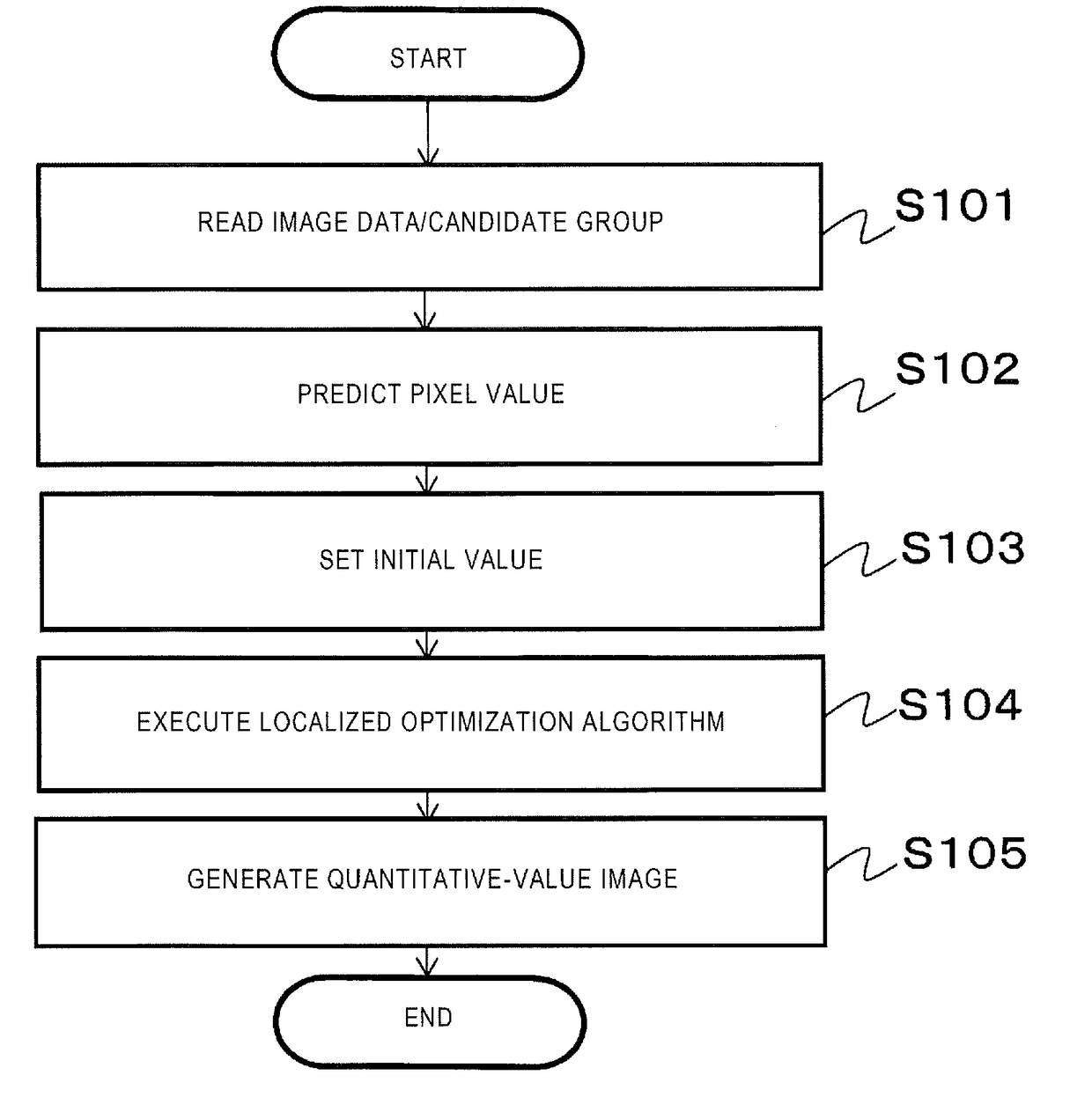
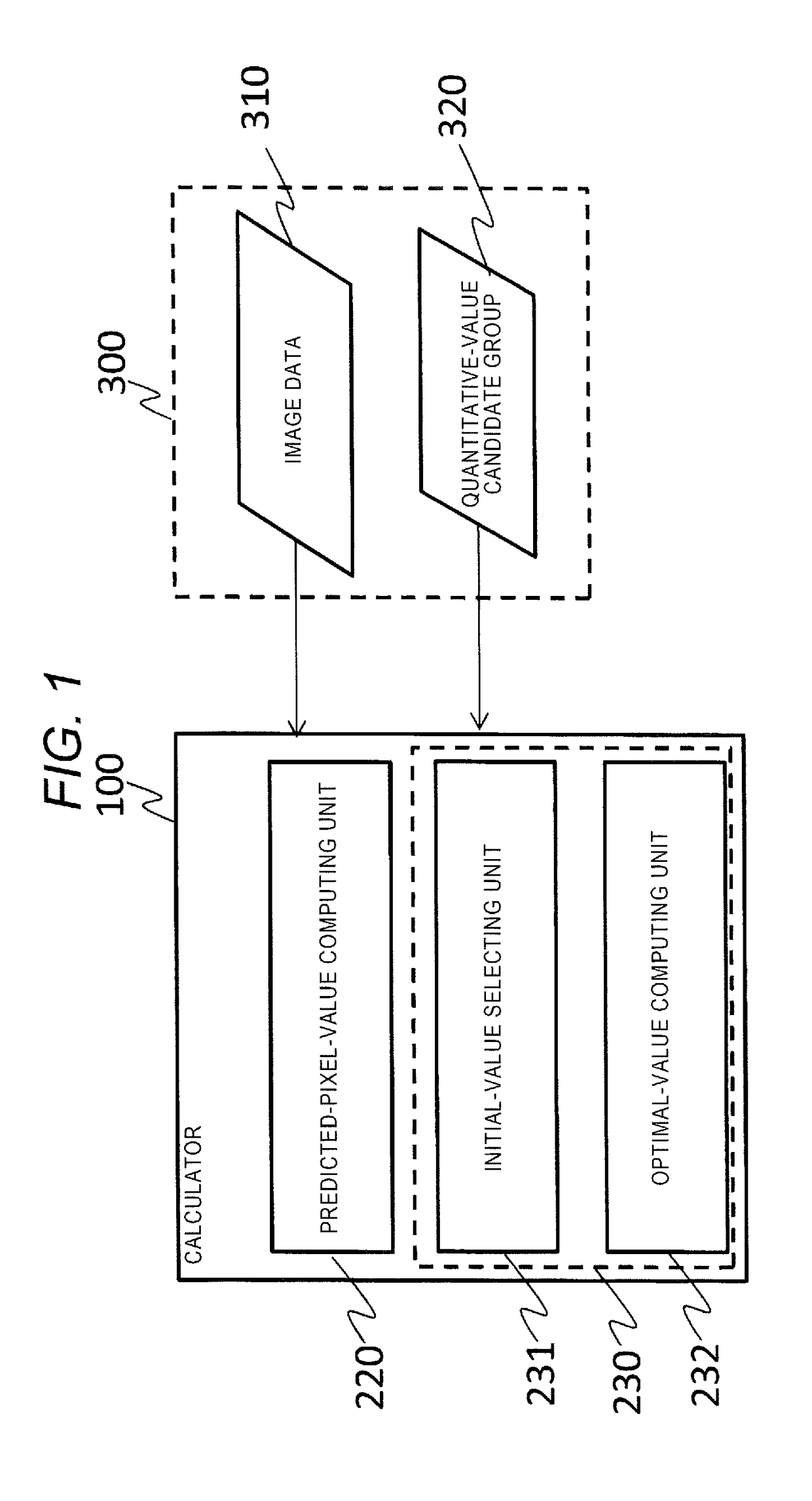
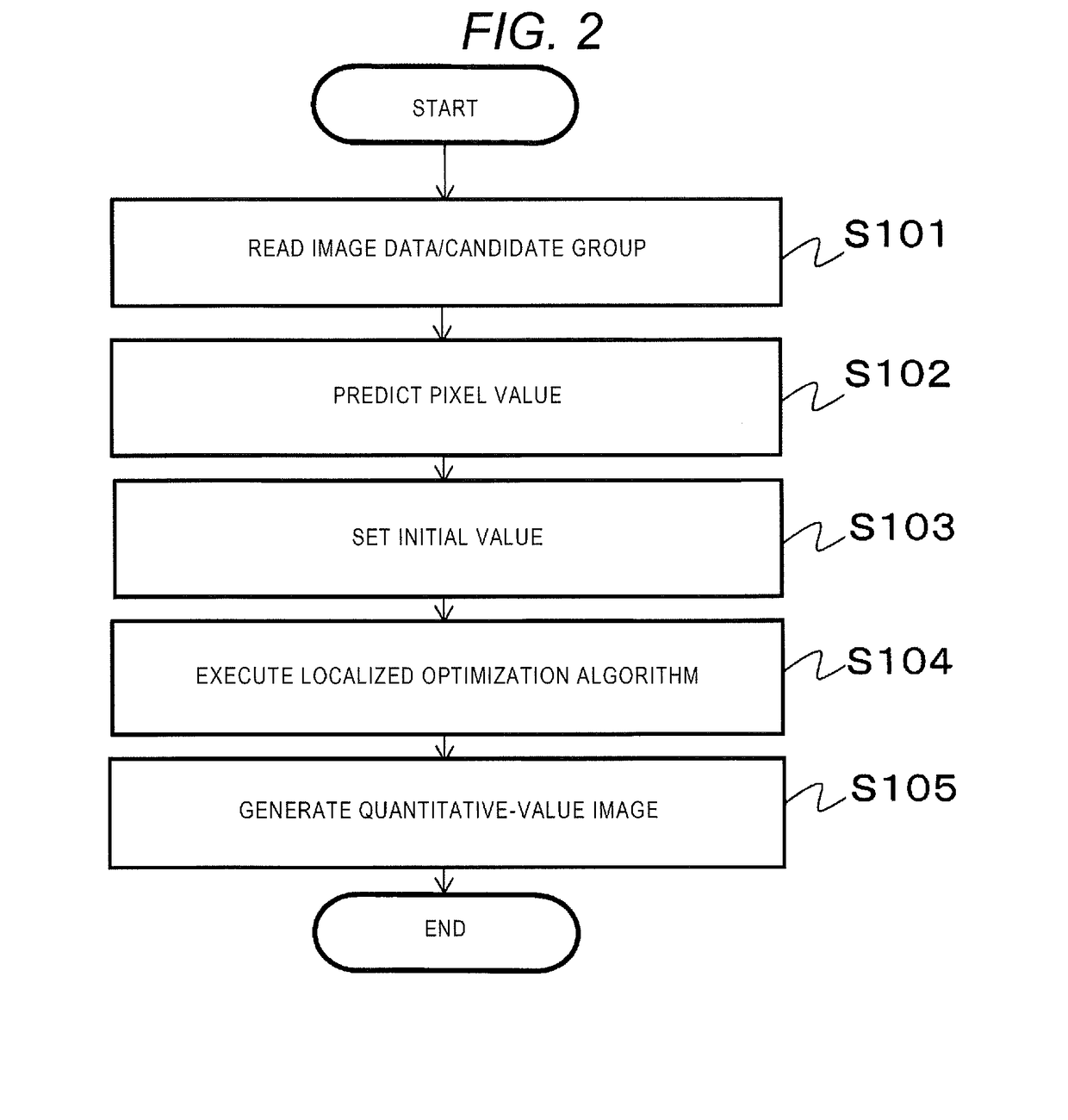
[0029]The embodiment is characterized by a calculator that performs quantitative value calculation using a plurality of images having different pixel values, which are obtained by performing imaging a plurality of times with different imaging parameter values in the same pulse sequence, the calculator including: a predicted-pixel-value computing unit that predicts a predicted value of a pixel value that is acquired from the imaging parameters in the imaging performed the plurality of times; an initial-value selecting unit that selects a quantitative-value candidate group which is used as initial values in quantitative value calculation from a plurality of predetermined quantitative-value candidate groups with reference to the pixel value predicted by the predicted-pixel-value computing unit; and an optimal-value computing unit that computes a quantitative value through a localized optimization technique using the initial value selected by the initial-value selecting unit. In additio...

second embodiment

[0041]The MRI apparatus of the embodiment includes the imaging unit, a measurement control unit that controls the imaging unit and measures data that is required for the quantitative value computation, and the calculator that performs the quantitative value computation. The measurement control unit performs imaging a plurality of times with different imaging parameters in the same pulse sequence, and acquires a plurality of images (image data) having different pixel values. The calculator includes the quantitative-value computing unit that performs the quantitative value computation by using information of the plurality of image data acquired through imaging and the predetermined quantitative-value candidate groups.

[0042]First, an entire configuration of the MRI apparatus that is common in the embodiments of the invention including the embodiment is described with reference to FIG. 4. FIG. 4 is a block diagram illustrating a common configuration of an MRI apparatus 10. The MRI appar...

third embodiment

[0091]The MRI apparatus of the embodiment is characterized in that the calculator is provided with separate means for computing a specific quantitative value, of the plurality of the quantitative-value candidates which are to be calculated, and thereby the computation speed is further improved. The MRI apparatus of the embodiment basically has the same configuration as the first embodiment. Hereinafter, a configuration different from that of the first embodiment will be described with a focus thereon. In addition, in the embodiment, a case where the separately computed specific quantitative value is the proportionality coefficient is described.

[0092]As illustrated in FIG. 9, a calculator 110C of the embodiment includes the configuration illustrated in FIG. 5A or 5B, in which the quantitative-value computing unit 230 further has a proportionality-coefficient computing unit 233 that computes an initial value of the proportionality coefficient. Except for this, the components assigned ...


PUM


Abstract

There is provided an MRI apparatus in which, when a quantitative value, which does not depend on imaging parameter values, is computed from a plurality of image data having different pixel values that are acquired by performing imaging the plurality of times with different imaging parameter values in the same pulse sequence, pixel values which are acquired from the imaging parameter values are predicted for each of a plurality of predetermined quantitative-value candidate group, and an initial value of the quantitative value is selected from the quantitative-value candidate groups with reference to the predicted pixel values. The optimal quantitative value is computed through a localized optimization technique using the selected initial value.

Description

BACKGROUND OF THE INVENTIONField of the Invention[0001]The present invention relates to a technology that generates a quantitative-value image in response to a signal acquired from a magnetic resonance imaging apparatus.Background Art[0002]A magnetic resonance imaging (hereinafter, MRI) apparatus is a medical diagnostic imaging apparatus that mainly uses a nuclear magnetic resonance phenomenon of protons. The MRI apparatus is capable of non-invasively imaging any cross section and is capable of acquiring information related to vital functions such as bloodstream or metabolic functions, in addition to morphological information. In general, a slice gradient magnetic field is applied to a subject positioned in a magnetostatic field and, simultaneously, a high-frequency magnetic field having a specific frequency is applied thereto, and thus nuclear magnetization is excited in a cross section that needs to be imaged. A phase-encoding gradient magnetic field and a lead-out gradient magnet...

Claims


Application Information

Patent Timeline
IPC IPC(8): A61B90/00H04N19/105
CPCA61B90/37A61B2090/374H04N19/105A61B5/055G01R33/54G01R33/543G01R33/5608G01R33/00G01R33/50G01R33/561
Inventor YOKOSAWA, SUGURUTANIGUCHI, YOOCHI, HISAAKIAMEMIYA, TOMOKISOUTOME, YOSHIHISA
Owner FUJIFILM HEALTHCARE CORP
Why Eureka
Eureka Blog
Learn More