Compression system

a compression system and compression tube technology, applied in the field of compression systems, can solve the problems of inefficiency and high cost of prior art natural gas compression systems, and achieve the effects of less fuel, less fuel burned, and less horsepower

Active Publication Date: 2018-02-01
PRECISION COMPRESSION LLC
View PDF3 Cites 2 Cited by
  • Summary
  • Abstract
  • Description
  • Claims
  • Application Information

AI Technical Summary

Benefits of technology

[0021]As the system of the preferred embodiment is adapted to operate at a maximum pressure of 600 psi, the system may be finely adjusted such that the system may be “dialed in” to operate over a wider range of operating parameters, at lower pressure, than conventional systems, while at the same time moving the same daily volume of raw gas as larger conventional systems. At 50 HP the system of the preferred embodiment will move more mcfg / HP than conventional units. Due to the maximum pressure of approximately 600 psi, it takes less horsepower to compress gas at this pressure than at the high pressures. The compressors of the preferred embodiment move the same volume as the high pressure units but at much lower horsepower requirements. The system of the preferred embodiment, therefore, can move more mcf / hp than the larger systems.
[0026]With the compact and efficient design of the system of the present disclosure, the ratio of mcf compressed versus the mcf burned as fuel is lower than conventional systems. Since the compressors of the present disclosure comprise lower horsepower requirements, less fuel is burned. In a mcf / hp comparison, the presently disclosed system burns less fuel than a conventional system.
[0027]Horizontal compressors take up much more horizontal space than a vertical compressor. Larger compressors, including those that operate at pressures of 1200 psi or more, weigh much more than the compressors of the present disclosure. The compact design and reduced weight of the system of the present disclosure allows for ease of delivery and efficient operation.

Problems solved by technology

Prior art natural gas compression systems are often inefficient and expensive.

Method used


Image

  • Compression system
  • Compression system

Examples


Embodiment Construction

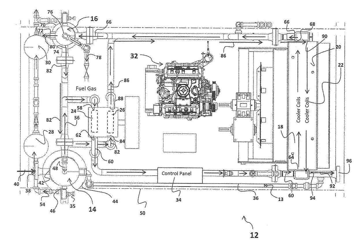
[0029]Referring to FIG. 1, there is shown the improved compression system 12 in accordance with preferred embodiments. As used herein, the terms “a” or “an” shall mean one or more than one. The term “plurality” shall mean two or more than two. The term “another” is defined as a second or more. The terms “including” and / or “having” are open ended (e.g., comprising). The term “or” as used herein is to be interpreted as inclusive or meaning any one or any combination. Therefore, “A, B or C” means “any of the following: A; B; C; A and B; A and C; B and C; A, B and C”. An exception to this definition will occur only when a combination of elements, functions, steps or acts are in some way inherently mutually exclusive.

[0030]Reference throughout this document to “one embodiment,”“certain embodiments,”“an embodiment,” or similar term means that a particular feature, structure, or characteristic described in connection with the embodiment is included in at least one embodiment of the present...


PUM


Abstract

The compression system comprises a main fluid inlet adapted to receive a production stream of natural gas; first and second stage scrubbers; first and second compression units; first and second heat exchange units; one or more liquid dump containers; and an engine. The engine operates within a range of 1600-2100 revolutions per minute and the compressed gas comprises a pressure within a range of 360-600 pounds per square inch. The system comprises a weight to thousand cubic feet of gas per day ratio of less than twenty.

Description

[0001]This application claims priority from provisional application 62 / 368,202 filed Jul. 29, 2016, the contents of which are incorporated by reference herein their entirety.BACKGROUND OF THE INVENTION1. Field of the Invention[0002]The present invention relates generally to a compression system and specifically to an improved compression system that may be used for natural gas production.2. Description of the Prior Art[0003]Gas that comes directly from the ground (“raw natural gas”) comprises various substances. Some substances are liquid and others are non-liquids. Prior to being transmitted through a gas pipeline, it is desirable to remove liquids from the gas so that the gas can be compressed and transported through the pipeline. Liquids can include water, natural gas condensate, and oil. Raw natural gas may also typically include contaminants such as carbon dioxide (CO2) and hydrogen sulfide (H2S).[0004]Raw natural gas is collected from a well or group of wells. This raw gas is ...

Claims


Application Information

Patent Timeline
Patent Type & Authority Applications(United States)
IPC IPC(8): F02M21/02F02F7/00
CPCF02M21/0215F02M21/0245F02F7/0082F02M21/023F02M21/0227F04D17/12
Inventor BENGE, BRIAN
Owner PRECISION COMPRESSION LLC
Why Eureka
Try Eureka