Constrained Motion with Reformable Guide Member

a technology of guide member and guide member, which is applied in the direction of mechanical equipment, rotary machine parts, other domestic objects, etc., can solve the problems of high cost of disassembly and replacement of bearing components, etc., to achieve simple and inexpensive construction, simple and low-cost design

Inactive Publication Date: 2018-02-08
KORN EDWARD
View PDF9 Cites 0 Cited by
  • Summary
  • Abstract
  • Description
  • Claims
  • Application Information

AI Technical Summary

Benefits of technology

[0018]In view of the foregoing disadvantages inherent in the design, manufacture, and assembly of sliding joints with guided motion in the prior art the present invention provides an improved design and method to simply and inexpensively build sliding joints with minimal clearance between the mating parts. The simplicity and low-cost of the design will be advantageous for many machines.
[0024]To achieve this purpose the present invention essentially comprises a design and method of forming precise bearing surfaces in place that eliminates the need for expensive machining of sliding components and also provides for the ability to conveniently and inexpensively reform sliding bearing components in place without the need to disassemble machine components. The design can use materials that reduce friction and damp vibration in a machine.
[0026]The method also includes the ability to use hardenable fluids that can be re-liquefied in place, for example by melting, and allowed to re-harden. When used in this embodiment the method allows worn bearing surfaces to be completely reformed in place without the need for disassembly of the machine or device.
[0027]The invention enables many sliding elements of a machine tool or other device to be constructed of components with relatively relaxed tolerances and then assembled into a final sliding construction with minimal clearances between components. This allows for accurate positioning and support and minimal friction in the desired direction of travel. Many different constructions which require accurately guided sliding motion can be fabricated using the invention.
[0031]It is therefore an object of the present invention to provide a new and improved design and method for producing guided sliding surfaces which enables machines and devices to be built with precise tolerances and lower manufacturing and assembly costs which has all of the advantages of prior art machines and none of the disadvantages.
[0032]It is another object of the present invention to provide sliding connections using a low friction material which are accurately located and have a long service life by virtue of the ability to easily reform the bearing material in place without the need for disassembly of a device.

Problems solved by technology

These machining operations are quite expensive and time-consuming and are also subject to error.
This is expensive and time-consuming because it requires various portions of the machine or device to be disassembled.
On some devices disassembly and replacement of bearing components is sufficiently expensive that the devices are discarded and not rebuilt once the bearing surfaces have worn.
In addition to requiring the costly purchase of new machines or devices discarding rather than repairing machines consumes energy and material resources.
That is to say it is less sustainable to discard machines than to design them so they can be conveniently repaired and reconditioned.

Method used


Image

  • Constrained Motion with Reformable Guide Member
  • Constrained Motion with Reformable Guide Member
  • Constrained Motion with Reformable Guide Member

Examples


Embodiment Construction

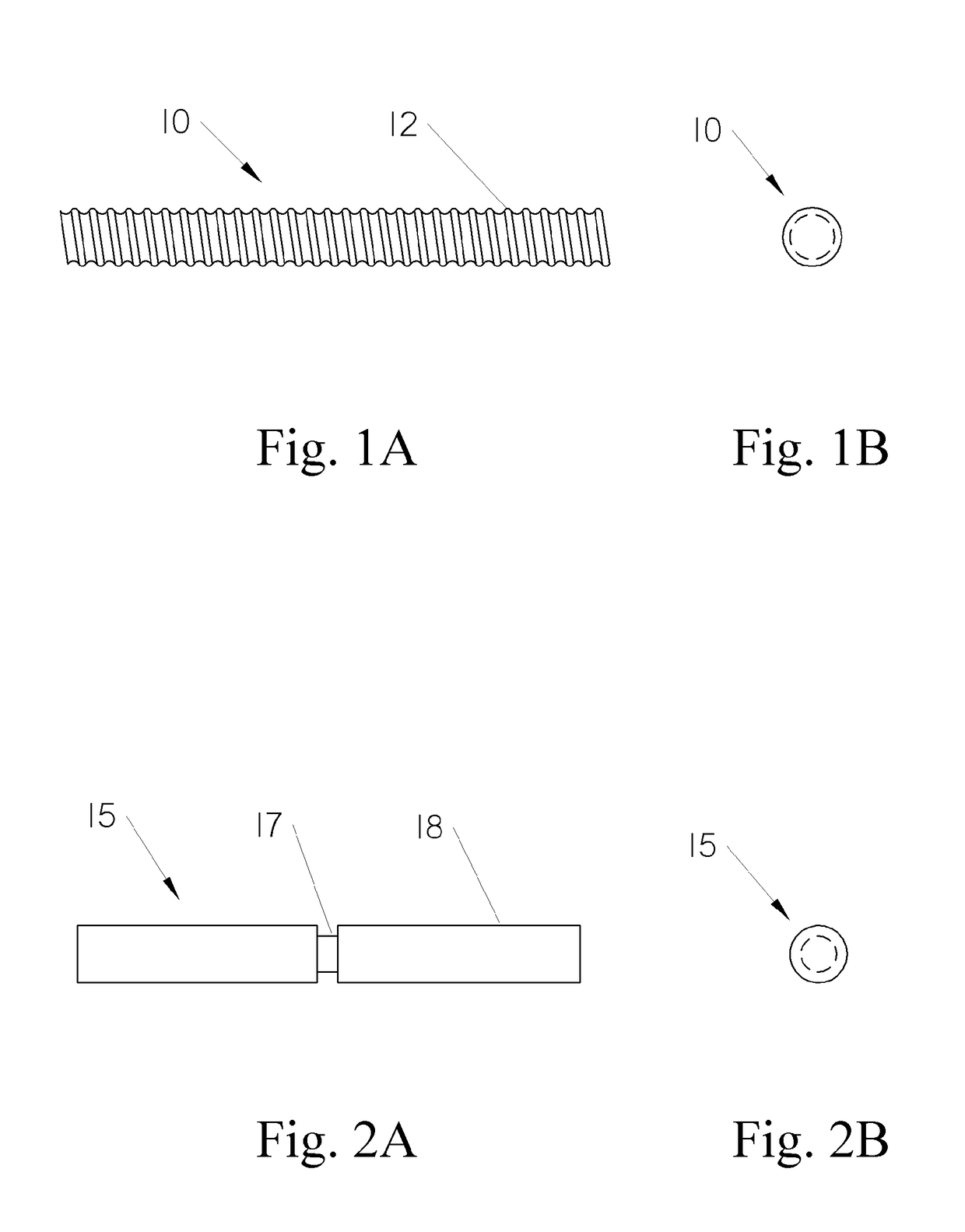
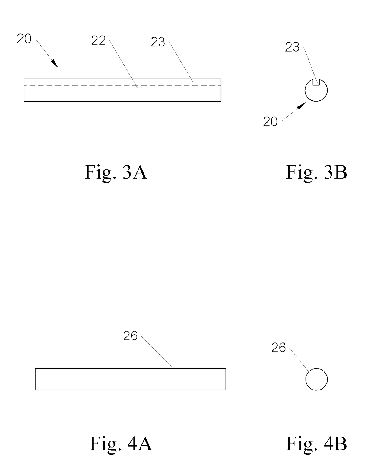
[0060]With reference now to the drawings, wherein like numerals designate like parts, FIG. 1A shows a side view of a leadscrew 10 with threads 12. FIG. 1B shows an end view of leadscrew 10. FIG. 2A shows a side view of shaft 15 with an annular groove 17 formed in body 18. FIG. 2B shows an end view of shaft 15. FIG.3A shows a side view of shaft 20 with a longitudinal groove 23 in body 22. FIG. 3B shows an end view of shaft 20. FIG. 4A shows a side view of shaft 26 and FIG. 4B shows an end view of shaft 26.

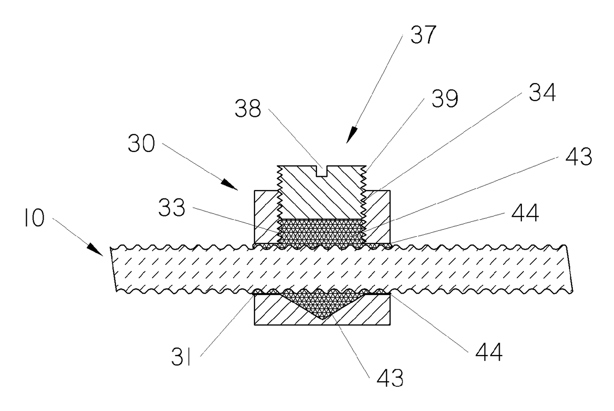
[0061]FIG. 5 shows a side view of rectangular nut 30 with a clearance hole 31 suitable for receiving any of the shafts shown in FIGS. 1-4. Nut 30 includes a cavity 33 in its top surface for receiving a slug of reformable material 36 and two mounting holes 35 for securing the nut to a machine tool member. Cavity 33 includes engaging means 34 along its edges. Cap 37 is configured with engaging means 39 and driving means 38.

[0062]FIG. 6 shows a top view of rectangular nut 30 showing ca...


PUM

PropertyMeasurementUnit
degrees of freedomaaaaaaaaaa

Abstract

An improved design and method is disclosed for constructing a sliding joint that constrains motion along or about one or more axes or directions and allows motion with low friction along or about a different axes or direction. The design simplifies the fabrication and assembly of sliding joints requiring accurate sliding alignment with minimal clearance between sliding members, such as milling machine bases, saddles, tables and columns. The design also enables driving means, such as those commonly found in machine tools using a leadscrew and nut, to be fabricated with essentially zero backlash at a very low cost. Finally, the design enables bearing surfaces to be reformed after they have worn without the need for disassembly of components. This allows for complete recovery of the original precisely guided configuration without the need to disassemble a machine. The simplicity and low cost of the method will be especially advantageous in the manufacture of machine tools intended for education and maker markets.

Description

BACKGROUND OF THE INVENTIONField of the Invention[0001]The present invention relates generally to the need in many types of machines and devices to constrain motion along or about certain axes or directions while facilitating low friction guided motion along or about other axes or directions. The invention enables a new method for the construction of sliding joints which are able to accurately guide motion along a desired axis or direction while constraining motion and providing strength and support along other axes or directions. Due to its simplicity and low cost the invention relates to many types of machines and devices including milling machines, vices, and lathes.Description of the Prior Art[0002]There is a well-known need in the machine art for accurately guided motion. There are often significant forces involved in guiding or driving machine members so the means of constraining and guiding motion must be strong enough and rigid enough to withstand these forces.[0003]In machi...

Claims


Application Information

Patent Timeline
Patent Type & Authority Applications(United States)
IPC IPC(8): B29C45/00B29C45/14
CPCB29C45/0017B29C45/14336B29L2001/007B29K2705/00B29K2023/0683F16C29/02F16C2202/50F16C2322/39
Inventor KORN, EDWARD
Owner KORN EDWARD
Why Eureka
Try Eureka