Process integration of a gas processing unit with liquefaction unit

a gas processing unit and liquefaction unit technology, applied in the field of process integration of gas processing units with liquefaction units, can solve the problems of premature freezing of components within other parts thermal efficiency, and increased cost of the warm end of the heat exchanger, so as to achieve the effect of less cost, flexible method and efficient production method

Inactive Publication Date: 2018-02-08
LAIR LIQUIDE SA POUR LETUDE & LEXPLOITATION DES PROCEDES GEORGES CLAUDE
View PDF1 Cites 9 Cited by
  • Summary
  • Abstract
  • Description
  • Claims
  • Application Information

AI Technical Summary

Benefits of technology

[0010]The present invention is directed to a method and apparatus that satisfies at least one of these needs. In certain embodiments, the invention can provide a lower cost, more efficient and flexible method to produce LNG.
[0011]There is a demand to reduce the cost of liquefying a natural gas stream. In one embodiment of the present invention, a method for producing lower cost liquid natural gas is provided by integrating a syngas production facility, which can include a steam methane reformer (SMR), an autothermal reactor (ATR), or an ATR in combination with the SMR, with the LNG liquefaction unit.

Problems solved by technology

However, this pressure must also be maintained below the maximum allowable working pressure of the equipment design.
As a result, the warm end of the heat exchanger may receive more cold than is needed.
In addition to the loss of thermal efficiency, the warm end of the heat exchanger could get to a temperature that is colder than it was designed for, which could lead to structural issues, as well as premature freezing of components within other parts of the heat exchanger, particularly the heavy hydrocarbons.
In certain embodiments, all the expansion of the natural gas is carried out at ambient or warm temperatures, which results in limited risk of heavy hydrocarbon freezing at turbine outlets.

Method used


Image

  • Process integration of a gas processing unit with liquefaction unit
  • Process integration of a gas processing unit with liquefaction unit
  • Process integration of a gas processing unit with liquefaction unit

Examples


Embodiment Construction

[0138]While the invention will be described in connection with several embodiments, it will be understood that it is not intended to limit the invention to those embodiments. On the contrary, it is intended to cover all the alternatives, modifications and equivalence as may be included within the spirit and scope of the invention defined by the appended claims.

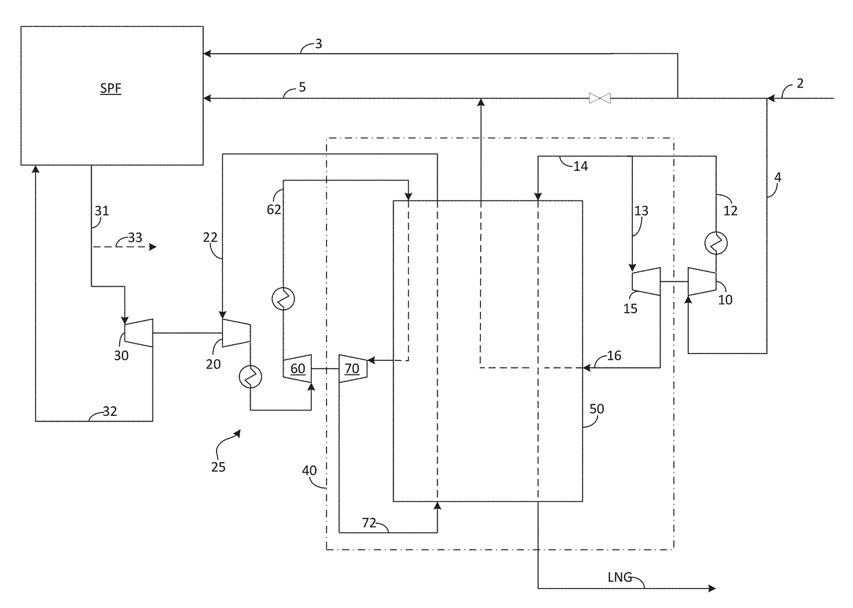
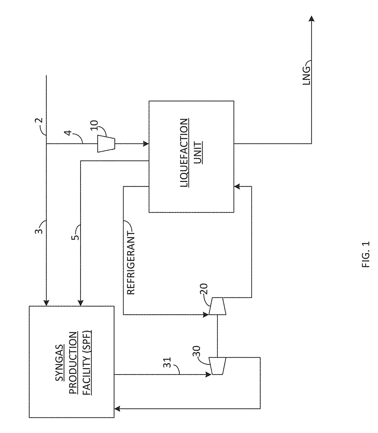
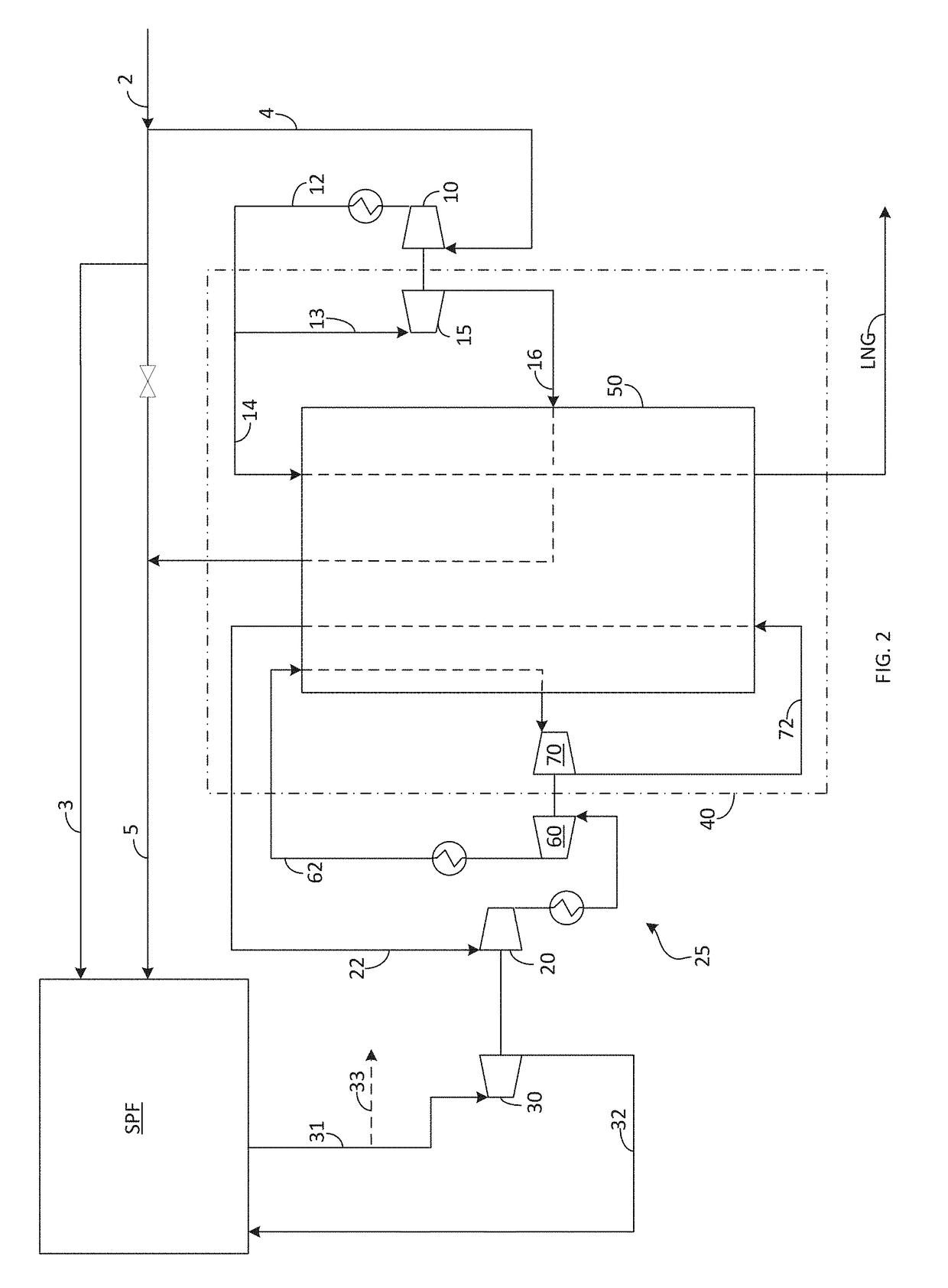
[0139]As shown in FIG. 23, it is proposed to integrate a gas processing unit with a liquefaction unit. There is a demand to reduce the cost of liquefying an industrial gas stream. The industrial gas stream may be but is not limited to air gases of oxygen, nitrogen argon, hydrocarbon, LNG, syngas or its components, CO2, or any other molecule or combination of molecules. It is proposed to integrate the underutilized process inefficiencies of a gas processing unit into the liquefaction unit to produce a liquid at a reduced operating cost. The gas processing unit may be any system or apparatus which alters the composition of a fee...


PUM

PropertyMeasurementUnit
freezing point temperaturesaaaaaaaaaa
freezing point temperatureaaaaaaaaaa
temperatureaaaaaaaaaa

Abstract

It is proposed to integrate a gas processing unit with a liquefaction unit. The industrial gas stream may be but is not limited to air gases of oxygen, nitrogen argon, hydrocarbon, LNG, syngas or its components, CO2, or any other molecule or combination of molecules. It is proposed to integrate the underutilized process inefficiencies of a gas processing unit into the liquefaction unit to produce a liquid at a reduced operating cost. The gas processing unit may be any system or apparatus which alters the composition of a feed gas. Examples could be, but are not limited to, a methanol plant, steam methane reformer, cogeneration plant, and partial oxidation unit.

Description

RELATED APPLICATIONS[0001]This application is a non-provisional application of U.S. Provisional Applicant No. 62 / 371,497, filed Aug. 5, 2016, which is herein incorporated by reference in its entirety.TECHNICAL FIELD OF THE INVENTION[0002]The present invention generally relates to a method for efficiently producing liquefied natural gas (LNG). More particularly, the present invention relates to a method for integrating LNG production with a syngas production facility, wherein pressurized steam from the syngas production facility is used to power a steam turbine, which in turn provides power for a recycle compressor of a refrigeration cycle used to liquefy the natural gas.BACKGROUND OF THE INVENTION[0003]Many locations utilize a high pressure (transmission) network and a lower pressure (distribution) network to supply natural gas through a local area. The transmission network typically acts as a freeway to economically send the gas over long distances to the general area, while the di...

Claims


Application Information

Patent Timeline
Patent Type & Authority Applications(United States)
IPC IPC(8): F25J1/02B01D53/047C01B3/56B01D53/48F25J1/00C01B3/34
CPCF25J1/023B01D2256/16F25J1/0228F25J1/0229F25J1/0072F25J1/0082F25J1/0234F25J1/005F25J1/001C01B3/34C01B3/56B01D53/48B01D53/047F25J2230/42F25J2230/22F25J2230/60F25J2290/60F25J2270/14F25J2200/06F25J2210/60F25J2215/04F25J2240/70F25J2240/12F25J2240/04F25J2270/04F25J2210/06F25J2230/04C01B2203/0216C01B2203/042C01B2203/1241C01B2203/1258C01B2203/061B01D2259/40086B01D2257/30B01D2256/24F25J1/0022F25J1/0015F25J1/0037F25J1/004F25J1/0045F25J1/0204F25J1/0221F25J1/0232F25J1/0236F25J1/0244F25J1/0245F25J1/0282F25J1/0288F25J1/0292F25J1/0294F25J3/04018F25J3/04024F25J3/04121F25J3/04412F25J3/04563F25J3/04593F25J3/046F25J2205/66F25J2210/12F25J2210/40F25J2210/42F25J2215/40F25J2220/64F25J2230/20F25J2230/30F25J2230/32F25J2230/40F25J2245/02F25J2245/40F25J2245/42F25J2260/44F25J2270/06F25J2270/16C01B2203/0233C01B2203/0244C01B2203/043C01B2203/046Y02P20/10F25J2210/02
Inventor ROESCH, ALEXANDERGUILLARD, ALAINTURNEY, MICHAEL A.
Owner LAIR LIQUIDE SA POUR LETUDE & LEXPLOITATION DES PROCEDES GEORGES CLAUDE
Why Eureka
Try Eureka