Blood Clot Aspiration Catheter

a technology of aspiration catheter and blood clot, which is applied in the field of thromboscopy catheter, can solve the problems of inefficient circulation, blood clots typically occurring, significant morbidity and mortality in the united states and throughout the world, and achieve the effect of eliminating clots from the catheter

Inactive Publication Date: 2018-02-15
BATISTE STANLEY
View PDF0 Cites 38 Cited by
  • Summary
  • Abstract
  • Description
  • Claims
  • Application Information

AI Technical Summary

Benefits of technology

[0015]A second embodiment of the design employs a parallel flush catheter alongside of the aspiration catheter to allow the operator to apply a fluid flush that is under pressure

Problems solved by technology

Deep vein thrombosis (DVT) is a common problem and causes significant morbidity and mortality in the United States and throughout the world.
These blood clots typically occur due to slow or reduced blood flow through the deep veins such as when the patient cannot ambulate or otherwise efficiently circulate their blood.
Another cause of inefficient circulation may be due to structural damage to the veins such as general trauma or subsequent to surgical procedures.
For example, a woman on birth control who smokes has an increased risk of forming blood clots and is thus predisposed to DVT.
For example, the clot may dislodge from a location in the deep vein of the patient's leg and migrate through the heart and come to rest in the patient's lung causing a pulmonary embolism (PE) resulting in restricted circulation and can cause sudden death for the patient.
This form of treatment has the disadvantage that the medication may cause bleeding at other sites such as within the brain.
For example, if a patient has previously had a minute non-clinical stroke, the medication used in a thrombolysis may cause a previously healed vessel to bleed within the patient's head.
This form of treatment can be technically challenging because the catheter must be steered or navigated to

Method used


Image

  • Blood Clot Aspiration Catheter
  • Blood Clot Aspiration Catheter
  • Blood Clot Aspiration Catheter

Examples


Embodiment Construction

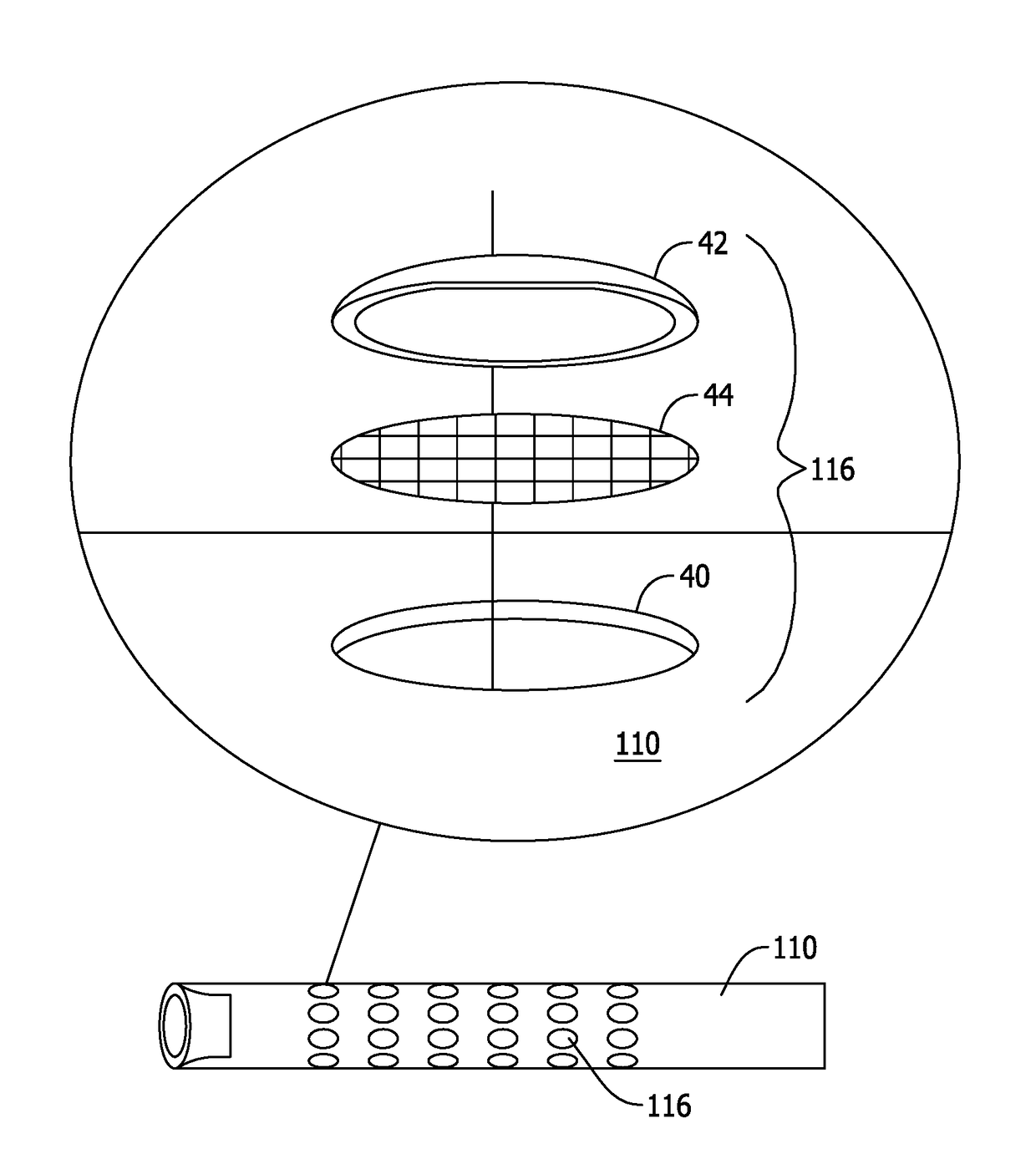
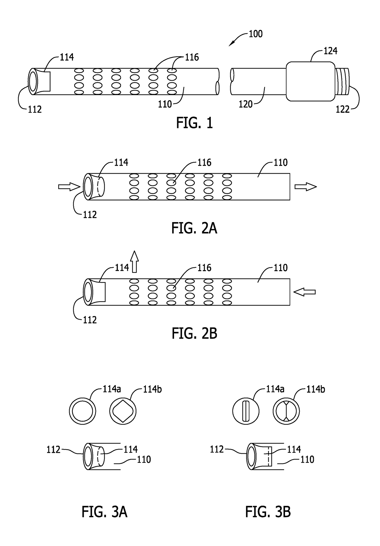
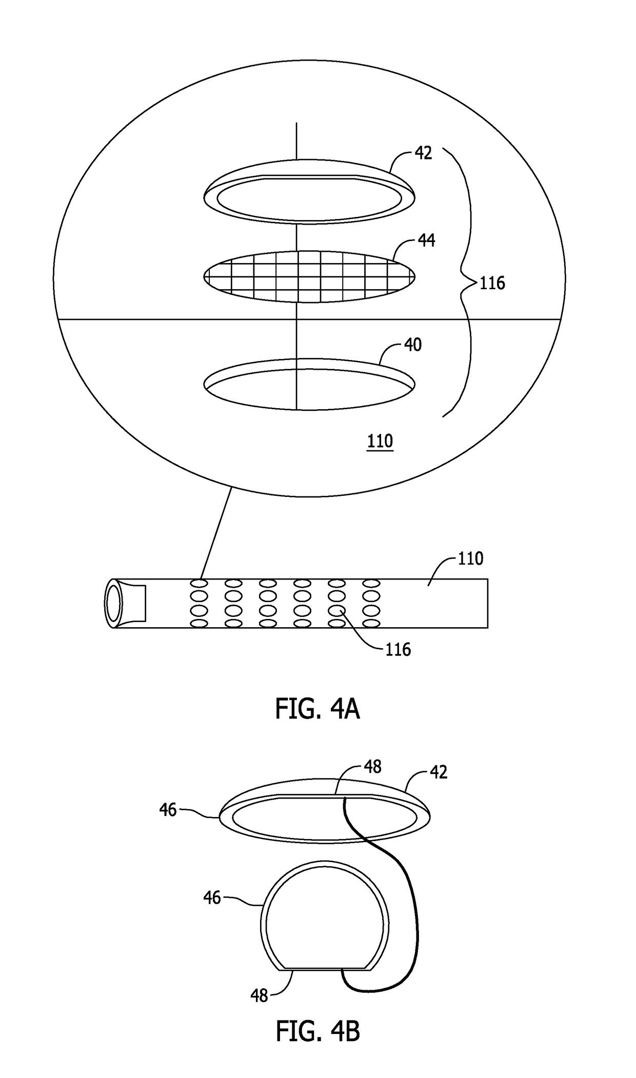
[0052]FIG. 1 is a segmented view of a blood clot aspiration catheter showing a proximal end and a distal end, according to an exemplary embodiment. A blood clot aspiration catheter 100 comprises a distal portion 110 and a proximal portion 120. The length extending from the distal portion 110 to the proximal portion 120 is not shown in FIG. 1, but is of sufficient length to access a blood vessel of a patient. The distal portion 110 comprises a distal end 112 to which a one-way valve 114 is attached. A plurality of micro-valves 116 are disposed on distal portion 110 of the catheter 100. The proximal portion 120 may comprise, for example a luer lock hub 122 and locking device 124 as is known in the art.

[0053]FIG. 2A shows the distal portion of the catheter of FIG. 1 with low pressure and flow toward the proximal end with the end valve open, and FIG. 2B shows the distal portion of the catheter of FIG. 1 with high pressure and flow directed toward the distal end with the end valve closed...


PUM


Abstract

A blood clot aspiration catheter includes an aspiration/flushing lumen having a distal portion that is insertable into a blood vessel of a patient, an aspiration device configured to create an aspiration phase to aspirate clot and blood into the aspiration/flushing lumen and a flushing phase to flush non-clotted blood from the aspiration/flushing lumen, a one-way valve configured to allow clot and blood to flow through the aspiration/flushing lumen during the aspiration phase and to block flow during the flushing phase, and filter valves configured to filter non-clotted blood to be flushed from the aspiration/flushing lumen.

Description

CROSS-REFERENCE TO RELATED APPLICATIONS[0001]This application claims priority to U.S. Provisional Application No. 62 / 373,846 which was filed on Aug. 11, 2016; U.S. Provisional Application No. 62 / 416,612 which was filed on Nov. 2, 2016; U.S. Provisional Application No. 62 / 420,425 which was filed on Nov. 10, 2016; U.S. Provisional Application No. 62 / 426,111 which was filed on Nov. 23, 2016; and U.S. Provisional Application No. 62 / 472,474 which was filed on Mar. 16, 2017. The contents of each of the above applications are incorporated by reference.BACKGROUND1. Field[0002]The disclosed embodiments relate to thrombectomy catheters which are used in the human vascular system to aspirate blood clots.2. Related Art[0003]Deep vein thrombosis (DVT) is a common problem and causes significant morbidity and mortality in the United States and throughout the world. DVT is caused when a blood clot forms in the deep veins of the legs. These blood clots typically occur due to slow or reduced blood fl...

Claims


Application Information

Patent Timeline
IPC IPC(8): A61B17/22A61M39/24
CPCA61B17/22A61M39/24A61M2205/7545A61B2017/22038A61B2017/22067A61B2017/22079A61M2039/2426A61B2217/007A61B17/22032A61B2017/22039A61B2217/005A61M25/007A61M25/0075A61M25/0082A61M2025/0078A61M1/79A61M1/85A61M25/00
Inventor BATISTE, STANLEY
Owner BATISTE STANLEY
Why Eureka
Try Eureka