

Particle separating system
- Summary
- Abstract
- Description
- Claims
- Application Information
AI Technical Summary
Benefits of technology
Problems solved by technology
Method used
Image

Examples
Embodiment Construction
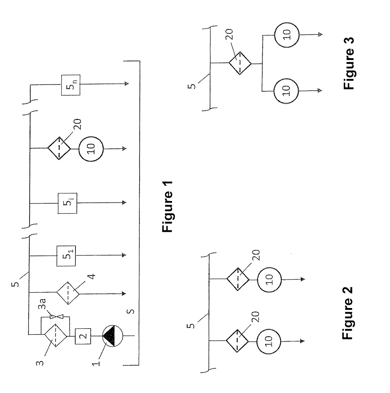
[0218]FIG. 1 shows a lubricating oil cycle for supplying an internal combustion engine with engine lubricating oil. The lubricating oil cycle comprises a lubricating oil reservoir S and a lubricating oil pump 1 which delivers engine lubricating oil from the lubricating oil reservoir S to consumption points 5i via a lubricating oil gallery 5, in order for example to lubricate a consumption point 5i and to cool, for example by means of spray cooling, and as applicable likewise lubricate a consumption point 5n. Once it has lubricated and / or cooled the relevant consumption point 5i, the lubricating oil flows back into the lubricating oil reservoir S.
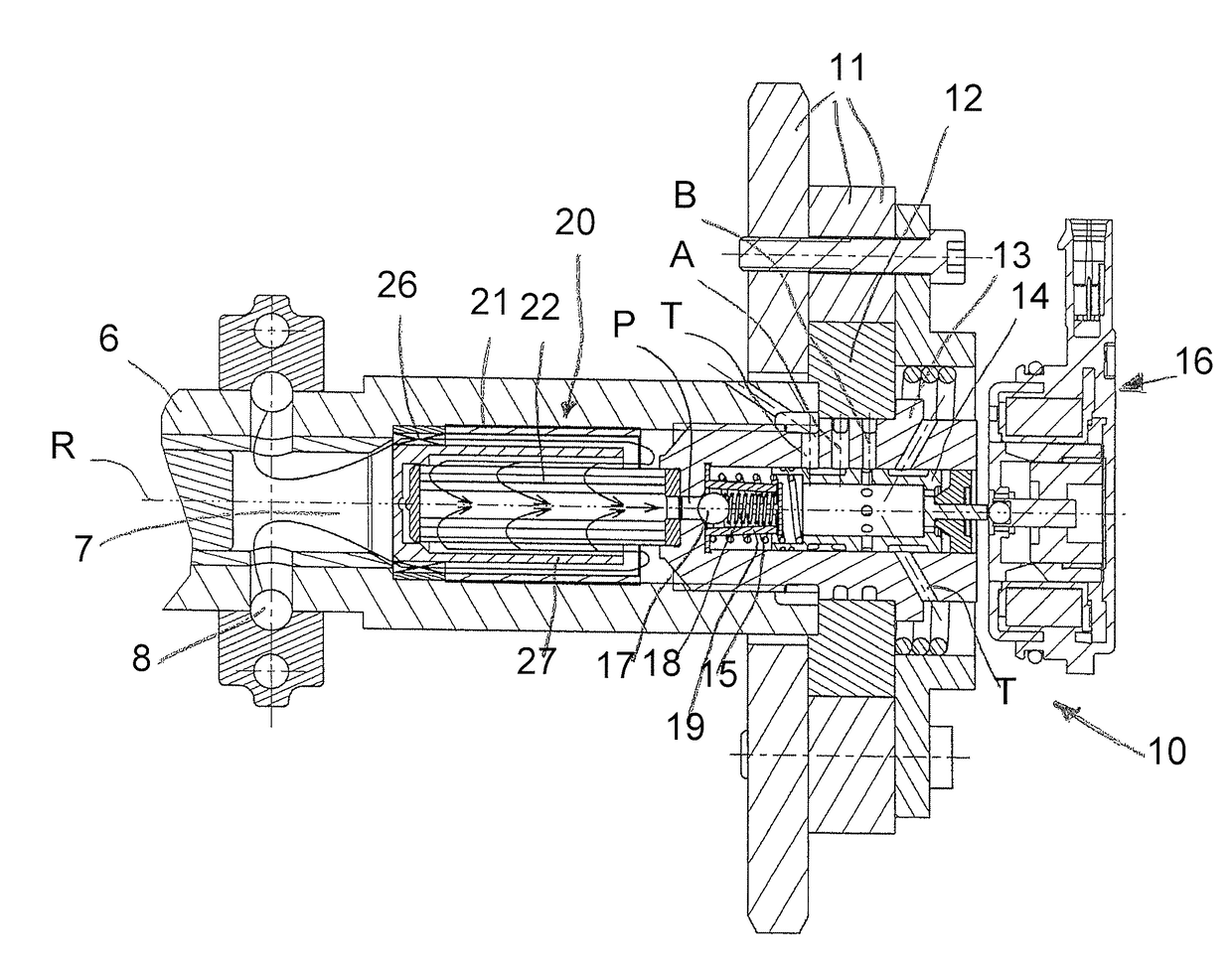
[0219]A cam shaft phase adjuster 10, referred to in the following as the phase adjuster 10, or a system of multiple phase adjusters 10 adjoins the lubricating oil cycle as an additional lubricating oil consumer. The engine lubricating oil serves as a pressure medium for the respective phase adjuster 10 for adjusting the phase position of a c...
PUM
| Property | Measurement | Unit |
|---|---|---|
| Fraction | aaaaa | aaaaa |
| Angle | aaaaa | aaaaa |
| Length | aaaaa | aaaaa |
Abstract
Description
Claims
Application Information