
Exercise Pool with Circulating Flow

Active Publication Date: 2018-02-15
HALL DAVID E
View PDF10 Cites 5 Cited by
  • Summary
  • Abstract
  • Description
  • Claims
  • Application Information

AI Technical Summary

Benefits of technology

The patent describes a self-contained swimming pool that has a propulsion system to create water currents for exercise, therapy, and rehabilitation purposes. The pool is designed for swimming and exercise against the current generated by the propulsion system. The pool has water return channels to allow the water currents to flow back to the propulsion system. The pool also has a seating surface for user seating on either side of the water currents. In some embodiments, the pool may have a balanced flow that better mimics actual swimming conditions for a better user experience.

Problems solved by technology

This results in velocity variations over the length of the tank.
The problem with such a design is that it requires a large swimming area and thus a large swimming tank.
Further, a large motor and great deal of power is required to circulate such a large volume of water.
The problem with such a tank is that large amounts of turbulence are developed, and loss of water velocity results.
Therefore, more power is needed to circulate the water, and swimming comfort is adversely affected by the turbulence.

Method used


Image

  • Exercise Pool with Circulating Flow
  • Exercise Pool with Circulating Flow
  • Exercise Pool with Circulating Flow

Examples


Embodiment Construction

—LISTING OF ELEMENTS FIGS. 1-16

[0042]

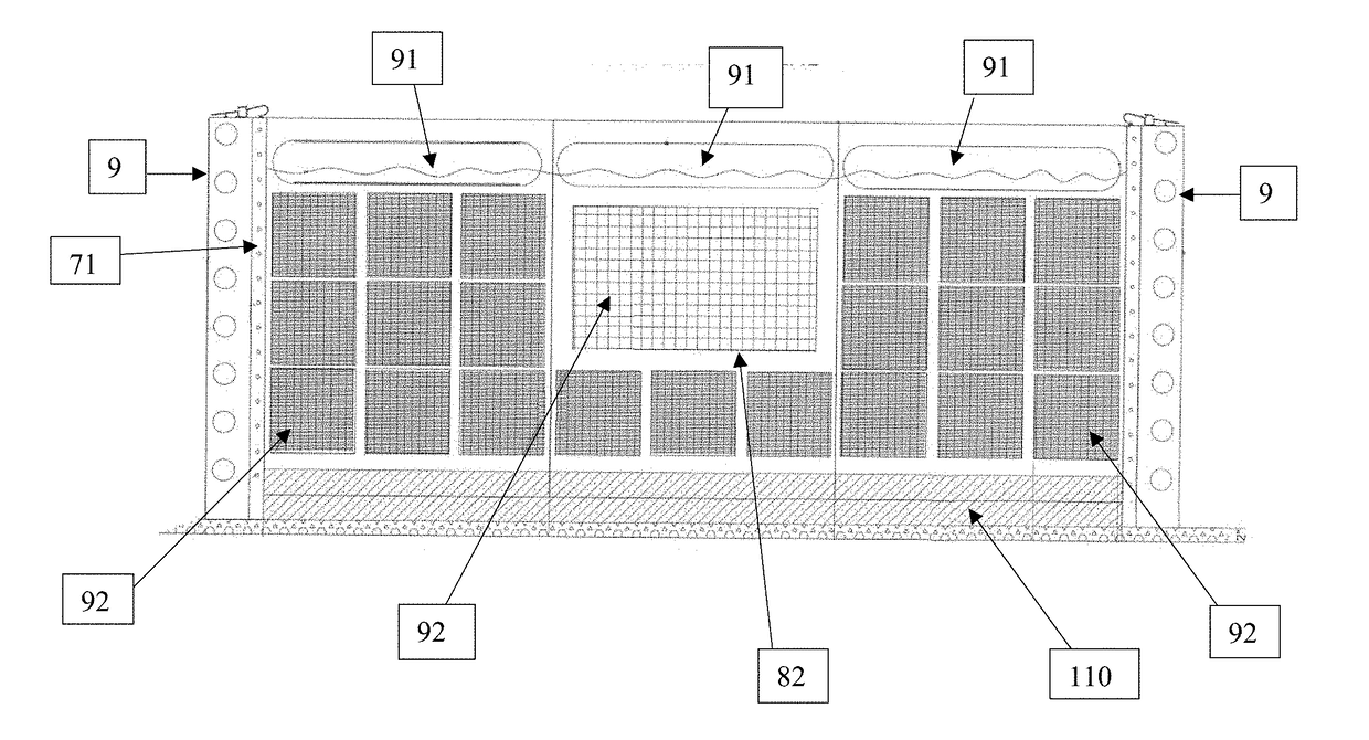
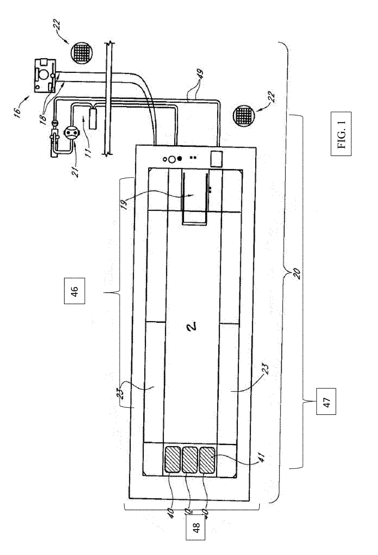
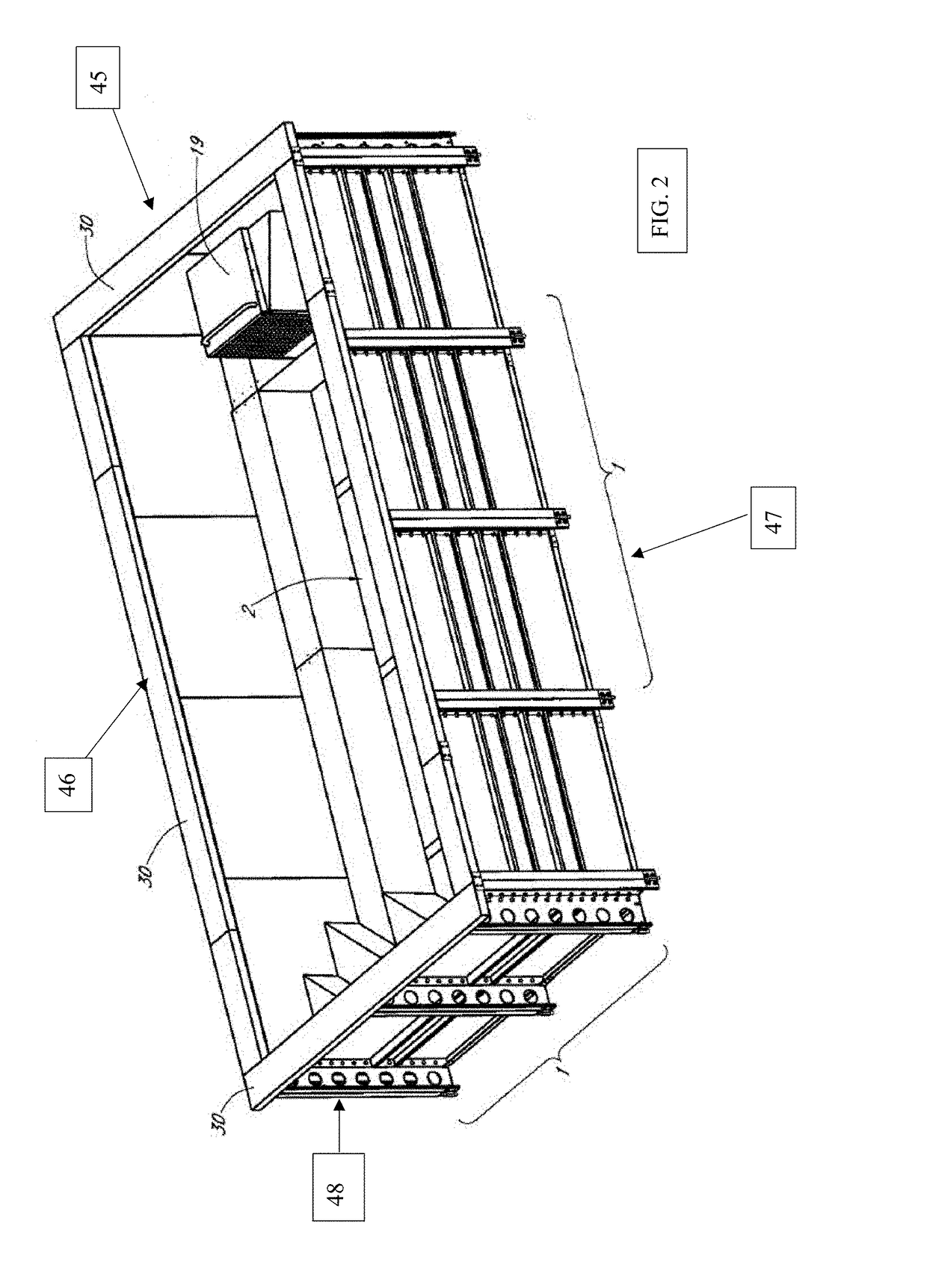
ELEMENT DESCRIPTIONELEMENT #Rigid Frame1Inner Water Containment Area2Water Return Channel3Propulsion System4Hydraulic System5Hydraulic Fluid6Coping7Decorative Horizontal Surface8Modular Interlocking Panels9Tension Straps10PVC Piping11Intentionally Blank12Mounting Strap13Housing14Intentionally Blank15Power System16Wall Support Covers17Hydraulic Line(s)18Propulsion System Housing19Self-contained Swimming Pool20Water Quality System21Drain22Underwater Benches23Horizontal Wall Supports24Current25Pool Panels (walls)27Pool Panel (interior side)28Pool Panel (exterior side)29Plain Walkway (8″)30Walkway (2′)3190 Degree Corner Supports32Top Corner Piece33Adjustable Screw Plate34Wall Seam Connecting Plate35Wall & Deck Support36Suction Tunnel37Seam Joint38Corner Tunnel39Water Return Inlet40Water Return Screen41Top Seat Pie Stiffener42Locking Slot43Bottom Wall Plate441st Side452nd Side463rd Side474th Side48Water Line49Fastener50

SUMMARY OF THE DISCLOSURE: FIGS....


PUM


Abstract

A Exercise Pool is disclosed herein having a rigid frame modular in design to allow for improved delivery and assembling. As shown the system may be configured with a box like structure providing containment of the flow head and may be configured with a removable walk deck having an air gap built in. As disclosed the treadmill swimming pool system as its general configuration is safer for users as it inhibits and / or eliminates hair and body entrapment. As disclosed it has a balanced flow which better replicates or reproduces actual swimming conditions for an enhanced user experience. The propulsion system may be controlled with a variable frequency drive (VFD) to allow for improved swimming conditions and control of same.

Description

CROSS REFERENCE TO RELATED APPLICATIONS[0001]Applicant states that this utility patent application is a continuation-in-part of U.S. patent application Ser. No. 14 / 064,968 filed on Oct. 28, 2013 which was a continuation of U.S. patent application Ser. No. 13 / 163,990 filed on Jun. 20, 2011 (now U.S. Pat. No. 8,607,372), which was a continuation of and claimed priority from U.S. patent application Ser. No. 11 / 986,572 filed on Nov. 23, 2007 (now U.S. Pat. No. 7,984,519), which claimed priority under 35 U.S.C. §119(e) of provisional U.S. Pat. Application Ser. No. 60 / 860,641 filed on Nov. 22, 2006, all of which are incorporated by reference herein in their entireties. Applicant also claims priority under 35 U.S.C. §119(e) of provisional U.S. Pat. Application Ser. No. 62 / 380,124 filed on Aug. 26, 2016, which is incorporated by reference herein in its entirety.STATEMENT REGARDING FEDERALLY SPONSORED RESEARCH OR DEVELOPMENT[0002]No federal funds were used to develop or create the invention ...

Claims


Application Information

Patent Timeline
IPC IPC(8): E04H4/00
CPCE04H4/005A63B69/125E04H4/0043
Inventor HALL, DAVID E.
Owner HALL DAVID E
Features
  • Generate Ideas
  • Intellectual Property
  • Life Sciences
  • Materials
  • Tech Scout
  • Unparalleled Data Quality
  • Higher Quality Content
  • 60% Fewer Hallucinations
Learn More