Target monitoring system and target monitoring method
a monitoring system and target technology, applied in the field of target monitoring systems, can solve the problem of becoming more difficult to predict the position of the target, and achieve the effect of improving the prediction accuracy of the target position
- Summary
- Abstract
- Description
- Claims
- Application Information
AI Technical Summary
Benefits of technology
Problems solved by technology
Method used
Image
Examples
first embodiment
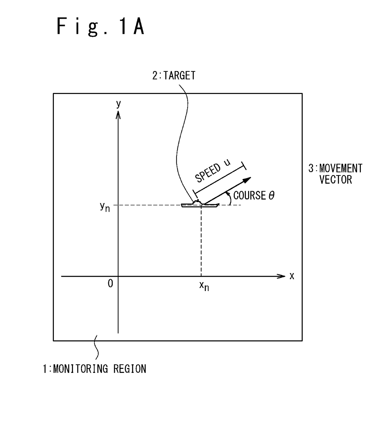
[0041]A case that a target to be monitored is a ship moving on the sea will be described. FIG. 1A is a plan view that showing a condition of a sea surface as an example of a monitoring region. Note that the target as a monitoring object may be a vehicle moving on land and so on.
[0042]FIG. 1A shows a sea region as a monitoring region 1 and a ship as a target 2 moving on the sea. The monitoring region 1 is regarded as a plane approximately and an orthogonal coordinate system (O, x, y) is defined on the plane. In this orthogonal coordinate system (O, x, y), the origin O is an optional point and may be a detection point of the target 2 at a detection start time t0. The X-axis passes through the origin O and is directed to an optional direction, and may be parallel to the meridian. The Y-axis is orthogonal to the X-axis at the origin O, and may be parallel to the latitude line.
[0043]In the orthogonal coordinate system (O, x, y), the position of the target 2 at an optional time tn is expr...
second embodiment
[0155]In the first embodiment, the reliability p0 of the detection has been described as the step S103 shown in the flow chart of FIG. 3. In the present embodiment, a handling method will be described when the reliability p0 of the detection is changed in the subsequent detections as a modification example of the first embodiment.
[0156]There is a case where it is proved during repeating the detection that the detection data received in the past is false. The false detection would be generated when an object different from the target 2 is erroneously regarded as the target. In such a case, the reliability of the detection data having been determined as the false detection is corrected to “0” and moreover the integration target distribution P is corrected, and then a predicted course probability since that time is recalculated. To make the recalculation possible, it is desirable that all the detection data are stored in the database 110. Note that the corrected integration target dist...
third embodiment
[0159]In the first embodiment, it has been described that the hypothesis courses 11 to 15 are previously generated in order to apply the Bayes' theorem and then the detection of the target 2 is carried out. However, actually, the necessity that the hypothesis routes 11 to 15 are corrected occurs while repeating the detection. In the present embodiment, as a modification example of the first embodiment, a method of changing the hypothesis routes after the the start of detection and applying a Bayes' theorem will be described.
[0160]FIG. 10A is a diagram when the target behavior hypothesis generating section according to the embodiment shows a state immediately before the hypothesis routes are corrected after the start of detection. In an example of FIG. 10A, the detection is starts after the hypothesis courses 11 to 15 are formed, like the case of FIG. 6A, and the detection positions 31 and 32 corresponding to the detection times t1 and t2 are respectively acquired. Referring to FIG. ...
PUM
 Abstract
Description
Claims
Application Information
 - R&D
- Intellectual Property
- Life Sciences
- Materials
- Tech Scout
- Unparalleled Data Quality
- Higher Quality Content
- 60% Fewer Hallucinations
Browse by: Latest US Patents, China's latest patents, Technical Efficacy Thesaurus, Application Domain, Technology Topic, Popular Technical Reports.
© 2025 PatSnap. All rights reserved.Legal|Privacy policy|Modern Slavery Act Transparency Statement|Sitemap|About US| Contact US: help@patsnap.com


