Tip clearance harmonic estimation

a harmonic estimation and rotorcraft technology, applied in the direction of rotorcraft, vehicles, aircrafts, etc., can solve the problems of not having the ability to predict direct measurements and not being able to gather additional state information

Active Publication Date: 2018-02-22
SIKORSKY AIRCRAFT CORP
View PDF2 Cites 20 Cited by
  • Summary
  • Abstract
  • Description
  • Claims
  • Application Information

AI Technical Summary

Problems solved by technology

However, since these direct measurements only measure the tip clearance at blade crossings, the direct measurements do not necessarily have predictive capability.
Also, since proximity sensors only provide tip clearance measurements, they cannot be used to gather additional state information.

Method used


Image

  • Tip clearance harmonic estimation
  • Tip clearance harmonic estimation
  • Tip clearance harmonic estimation

Examples


Embodiment Construction

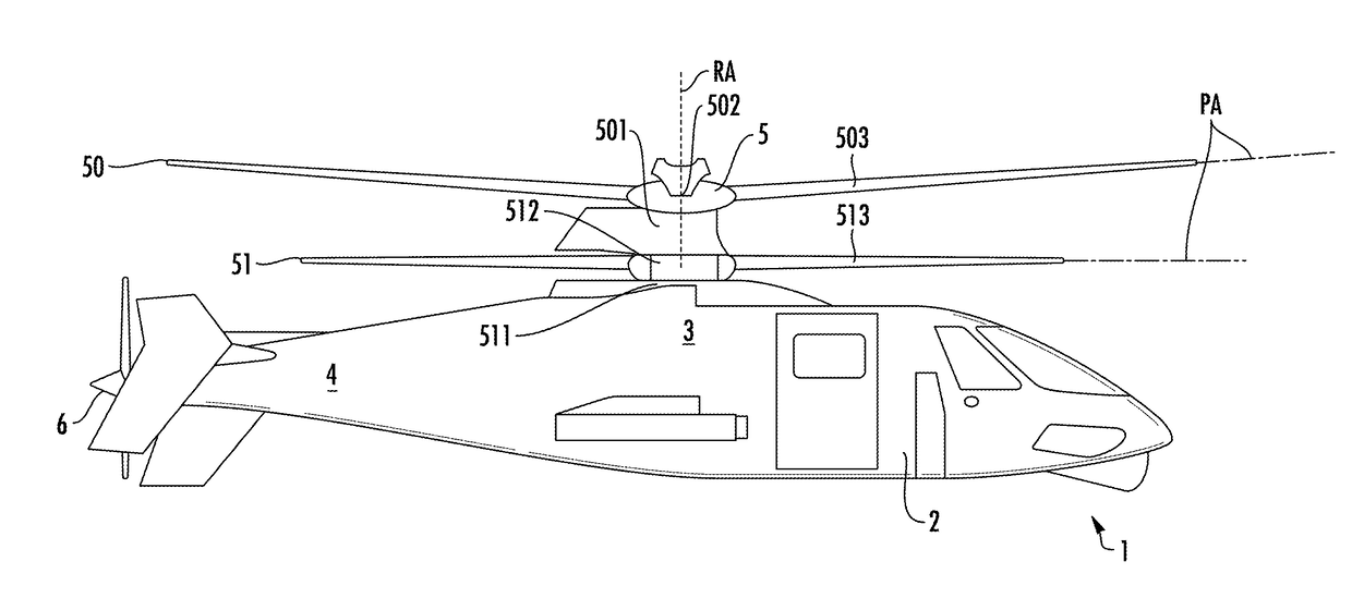
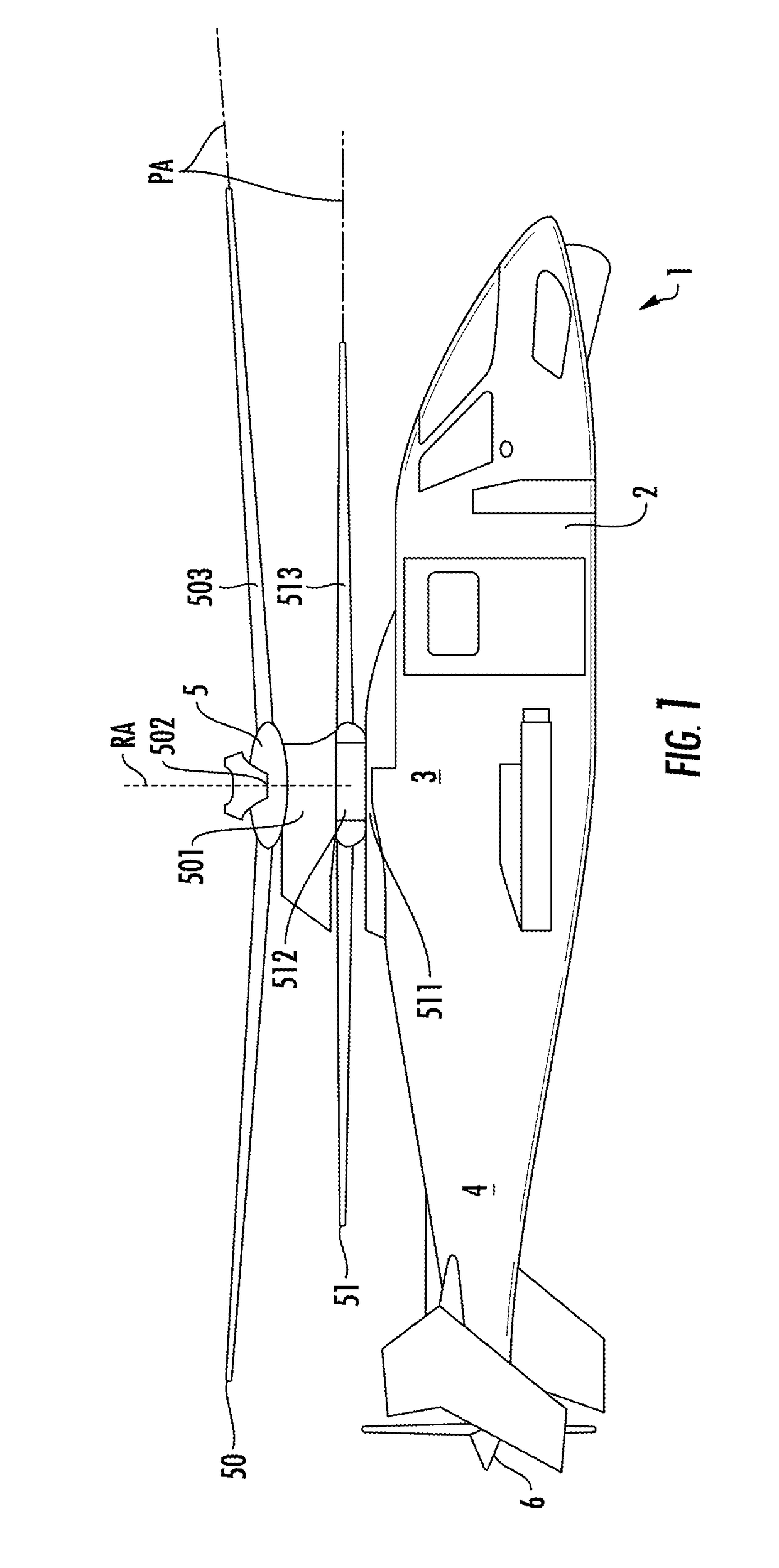
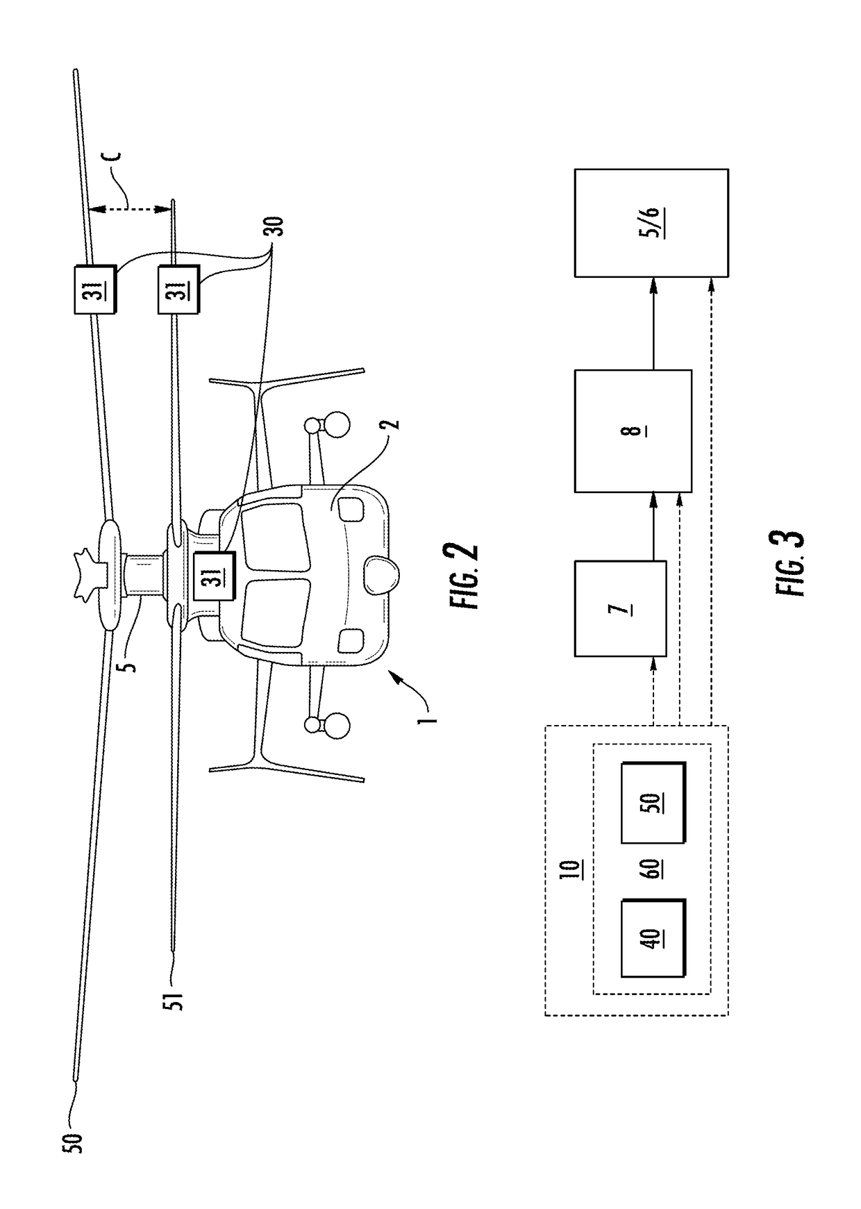
[0031]As will be described below, tip clearance of a coaxial rotorcraft is indirectly measured from readings indicative of blade deflection using a harmonic estimator. That is, the blade deflection of each rotor blade is measured using a strain-displacement method for example and a harmonic estimator is used to determine the harmonic components from the results of the strain-displacement method. With the harmonic components so determined, blade travel data as a function of azimuth can be predicted for both upper and lower rotors and thus a minimum tip clearance per revolution can be determined and maintained at every sample step independent of blade crossings.

[0032]With reference to FIGS. 1-3, a coaxial rotorcraft 1 is provided and may be configured for example as a coaxial, counter-rotating helicopter or some other fixed or variable wing aircraft with single or multiple rotors. The rotorcraft 1 has an airframe 2 that is sized to accommodate a pilot and, in some cases, one or more c...


PUM


Abstract

A method of tip clearance estimation for a rotor blade is provided. The method includes measuring blade deflection of the rotor blade, generating a harmonic function for the rotor blade from the measured blade deflection, predicting tip displacement of the rotor blade using the generated harmonic function and adjusting a position of the rotor blade according to the predicted tip displacement.

Description

STATEMENT REGARDING FEDERALLY SPONSORED RESEARCH OR DEVELOPMENT[0001]This invention was made with Government support under Agreement No. W911W6-13-2-0003 awarded by the Army. The Government has certain rights in the invention.BACKGROUND OF THE INVENTION[0002]The subject matter disclosed herein relates to a harmonic estimator and, more particularly, to a harmonic estimator for tip clearance in a rotorcraft.[0003]A coaxial rotorcraft is characterized as having an airframe and a main rotor assembly at a top portion of the airframe. The main rotor assembly includes upper and lower main rotors that rotate about a common rotational axis relative to the airframe in opposite directions to generate lift and thrust for the aircraft. Tip clearance between the respective blades of the upper and lower rotors refers to the distance between the blades of the upper rotor and the blades of the lower rotor as they pass one another during the rotations at blade crossings. Generally, tip clearance need...

Claims


Application Information

Patent Timeline
Patent Type & Authority Applications(United States)
IPC IPC(8): B64C27/00B64C27/57B64C27/10B64C27/58
CPCB64C27/008B64C27/57B64C27/10B64C27/58B64C27/006
Inventor GEIGER, DEREKBANNING, JEREMY FRIMPONG
Owner SIKORSKY AIRCRAFT CORP
Why Eureka
Try Eureka