Liquid crystal display panel

a liquid crystal display and display panel technology, applied in non-linear optics, instruments, optics, etc., can solve the problems of high manufacturing cost of the above-mentioned liquid crystal display panel, insufficient energy saving effect of the power saving mode, etc., to achieve better display effect for displaying images, low reflect ratio, and high reflect ratio

Inactive Publication Date: 2018-02-22
TCL CHINA STAR OPTOELECTRONICS TECH CO LTD +1
View PDF2 Cites 0 Cited by
  • Summary
  • Abstract
  • Description
  • Claims
  • Application Information

AI Technical Summary

Benefits of technology

[0006]In view of this, the present invention provides a liquid crystal display panel which has a high reflect ratio and a better display effect for displaying images, so as to solve the technical problem: a traditional liquid crystal display panel easily has a low reflect ratio and is poor in color mixture.
[0027]By disposing the transmission display area and the reflection display area, the liquid crystal display panel according to the present invention can sufficiently use an ambient light in a power saving situation, so that it has a high reflect ratio and a better color image display effect, so as to solve the technical problem: a traditional liquid crystal display panel easily has a low reflect ratio and is poor in color mixture.

Problems solved by technology

However, the manufacturing cost of the above-mentioned liquid crystal display panel is higher, and the energy saving effect thereof under the power saving mode is not good enough.

Method used


Image

  • Liquid crystal display panel
  • Liquid crystal display panel
  • Liquid crystal display panel

Examples


Embodiment Construction

[0034]Referring to the drawings, wherein the same reference numbers stand for same assemblies. The descriptions below are based on specific embodiments of the illustrated present disclosure, and the specific embodiments should not be considered as a limitation to other specific embodiments not described herein.

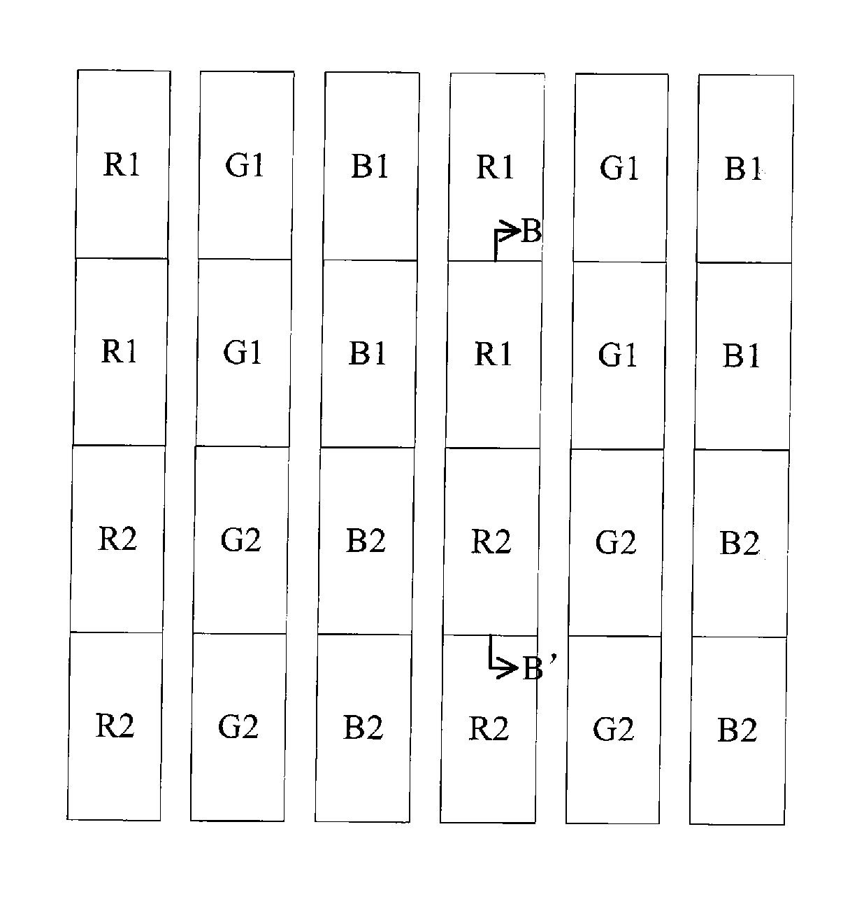
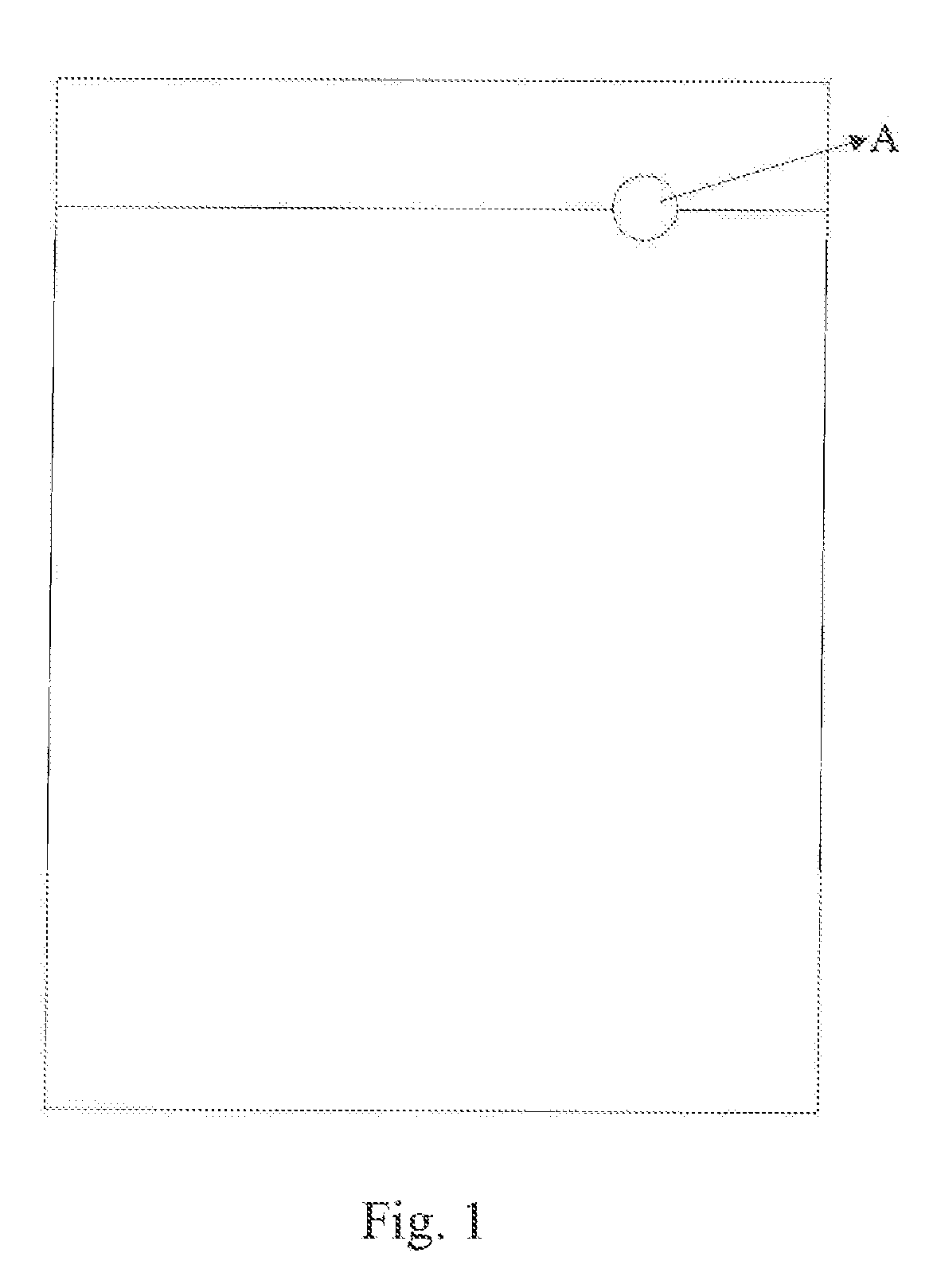
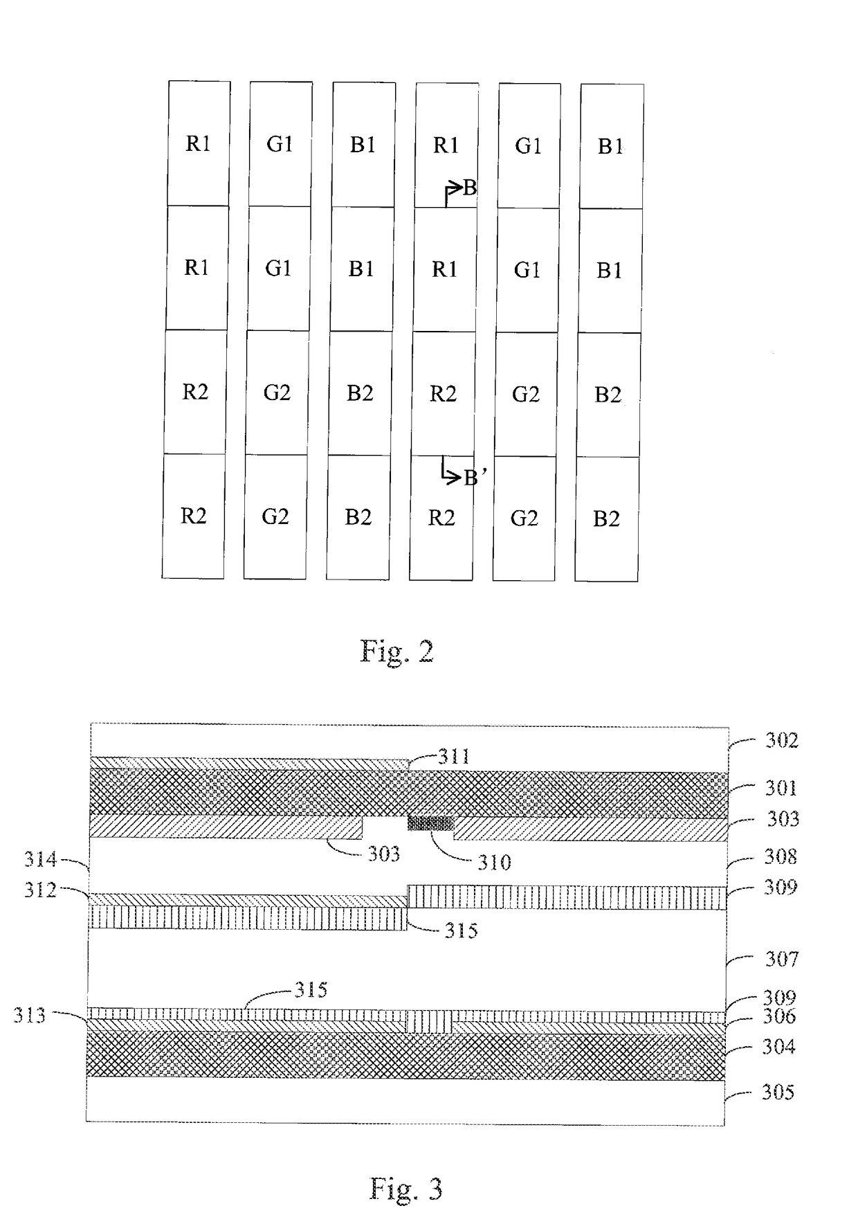
[0035]Refer now to FIG. 1 to FIG. 3, wherein FIG. 1 is a schematic structural view of a liquid crystal display panel according to a preferred embodiment of the present invention; FIG. 2 is an partial enlarged view of an A-part in FIG. 1; and FIG. 3 is a cross section view of a cross section line B-B′ of FIG. 2.

[0036]As shown in FIGS. 1 and 2, the liquid crystal display panel according to the preferred embodiment comprises a transmission display area and a reflection display area, wherein the transmission display area displays an image by a light transmission of a backlight light source, and the reflection display area displays an image by a reflection of an exterior ambient li...


PUM

PropertyMeasurementUnit
included angleaaaaaaaaaa
areaaaaaaaaaaa
color wavelengthaaaaaaaaaa

Abstract

A liquid crystal display panel is provided. The liquid crystal display panel has a transmission display area and a reflection display area. The transmission display area has an upper substrate, an upper polarizer, a color filter, a lower substrate, a lower polarizer, a first pixel electrode and a liquid crystal layer; and the reflection display area has the upper substrate, a half wave plate, the upper polarizer, the color filter, a common electrode, the lower substrate, a second pixel electrode and the liquid crystal layer.

Description

FIELD OF THE INVENTION[0001]The present invention relates to a liquid crystal display field, and more particularly to a liquid crystal display panel.BACKGROUND OF THE INVENTION[0002]With the gradual development of products and applications of wearable devices, such as intelligent watches, intelligent glasses, etc., given a fixed quantity of electricity of a battery, the endurance ability of the whole of the product will be greatly influenced by an energy consumption issue, so that the development of a low-consumption / high-performance display is important.[0003]According to an analysis of the purpose and the habits of people using liquid crystal display panels, a high performance display is necessary (high resolution, high contrast, high color gamut, etc.), but as an alternative, a low-consumption / low-performance display, may be selected in some application situations.[0004]In other words, when watching a video or image, the high-performance liquid crystal display panel is used to pr...

Claims


Application Information

Patent Timeline
Patent Type & Authority Applications(United States)
IPC IPC(8): G02F1/1335G02F1/1343G02F1/1337
CPCG02F1/133528G02F1/1343G02F1/133514G02F1/1337G02F1/133512G02F1/1333G02F1/133553G02F1/1336G02F1/13363G02F1/134363G02F1/133357G02F1/133638G02F1/134372G02F1/133555G02F1/139
Inventor CUI, HONGQINGZHONG, XINHUI
Owner TCL CHINA STAR OPTOELECTRONICS TECH CO LTD
Why Eureka
Try Eureka