Thermionic emission device, focus head, x-ray tube and x-ray emitter

a technology of x-ray emitter and x-ray emission device, which is applied in the direction of discharge tube main electrode, x-ray tube, radiation generation arrangement, etc., can solve the problems of main emitter and emitter cooling down with a time delay, and achieve the effect of reducing radiation exposure to a patien

Active Publication Date: 2018-02-22
SIEMENS HEALTHCARE GMBH
View PDF0 Cites 0 Cited by
  • Summary
  • Abstract
  • Description
  • Claims
  • Application Information

AI Technical Summary

Benefits of technology

The invention provides a thermionic emission device, a focus head, an x-ray tube, and an x-ray emitter that overcome the disadvantages of previous devices and reduce patient radiation exposure to x-rays through dose-modulated x-ray recordings. The device is designed to accelerate cooling of the main emitter by using a heat emitter at a more positive heating potential, preventing further electron emission in the main emitter direction. This results in faster cooling of the main emitter and improved dose modulation. The device can easily be used with an x-ray tube to produce images with reduced radiation exposures and shorter imaging recording times.

Problems solved by technology

Due to the missing electron emission from the heat emitter, the main emitter (image emitter) likewise cools down with a time delay.

Method used


Image

  • Thermionic emission device, focus head, x-ray tube and x-ray emitter
  • Thermionic emission device, focus head, x-ray tube and x-ray emitter
  • Thermionic emission device, focus head, x-ray tube and x-ray emitter

Examples


Embodiment Construction

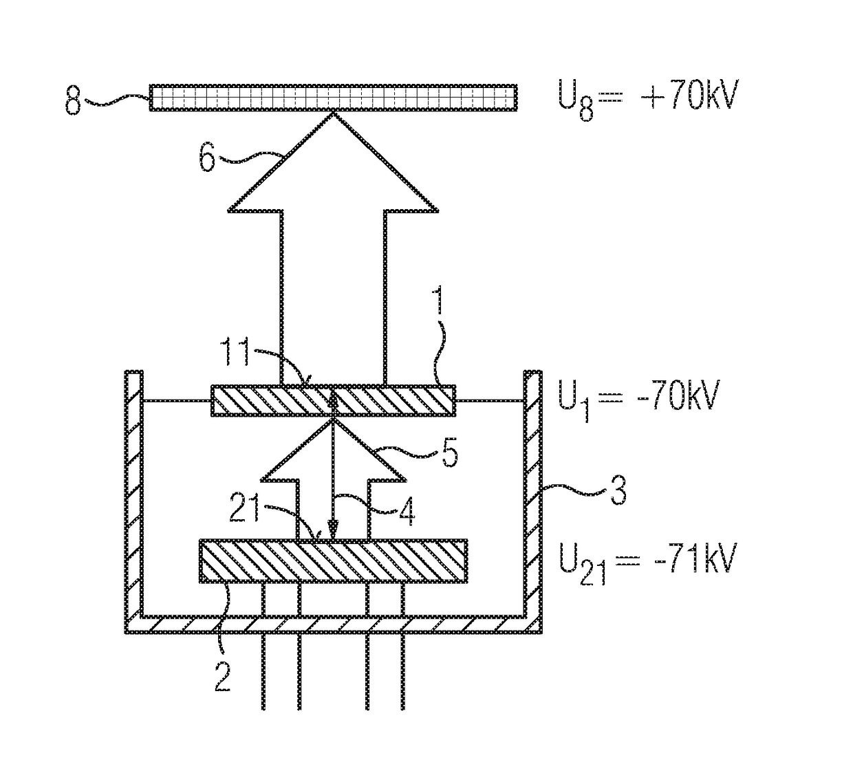
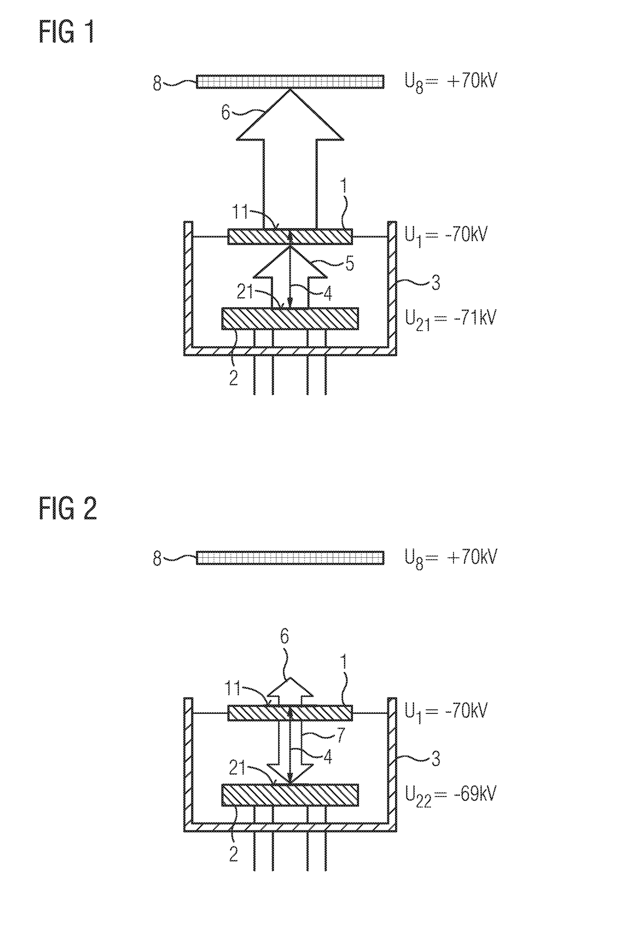
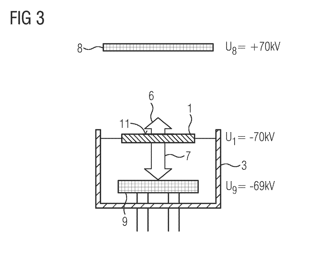
[0029]Referring now in detail to the figures of the drawings and first, particularly, to FIGS. 1 and 2 thereof, there is seen a thermionic emission device in accordance with the invention which includes an indirectly heatable main emitter 1 with a main emission surface 11 and a connectible heat emitter 2 with a heat emission surface 21.

[0030]The main emitter 1 and the heat emitter 2 are disposed together in a focus head 3. The main emitter 1 is held mechanically in the focus head 3 and is connected in an electrically conducting manner thereto.

[0031]In contrast, the heat emitter 2 is held mechanically in the focus head 3, but is electrically insulated from the focus head 3. The heat emitter 2 can thus be switched independently of the main emitter 1.

[0032]Furthermore, the main emitter 1 and the heat emitter 2 are distanced from one another in such a way that the heat emission surface 21 and the main emission surface 11 run at a predefinable distance 4 and substantially in parallel wit...


PUM


Abstract

A thermionic emission device includes an indirectly heatable main emitter with a main emission surface and a connectible heat emitter with a heat emission surface. The heat emission surface is disposed at a predefinable distance from the main emission surface. In the operating state, the main emitter is at a constant main potential and the heat emitter can be switched between at least two heating potentials which differ from one another and which differ from the main potential. Through the use of the thermionic emission device, the radiation load for a patient is reduced in the case of dose-modulated x-ray recordings.

Description

CROSS-REFERENCE TO RELATED APPLICATION[0001]This application claims the priority, under 35 U.S.C. § 119, of German Patent Application DE 10 2016 215 378.1, filed Aug. 17, 2016; the prior application is herewith incorporated by reference in its entirety.BACKGROUND OF THE INVENTIONField of the Invention[0002]The invention relates to a thermionic emission device. The invention also relates to a focus head, an x-ray tube and an x-ray emitter.[0003]A thermionic emission device of that type is known from German Patent DE 10 2009 005 454 B4, corresponding to U.S. Pat. No. 8,227,970, for instance, and in an x-ray tube functions as a cathode. The known thermionic emission device includes an indirectly heated main emitter, which is embodied as a flat emitter with an unstructured main emission surface and with a heat emitter which is embodied as a flat emitter with a structured heat emission surface. The main emitter and the heat emitter each have at least two connecting lugs, wherein the main...

Claims


Application Information

Patent Timeline
IPC IPC(8): H01J35/10H01J35/14
CPCH01J35/14H01J35/105H01J1/20H01J1/22H01J2235/06H01J35/064A61B6/40H05G1/10H01J35/065H01J35/06
Inventor FRITZLER, ANJA
Owner SIEMENS HEALTHCARE GMBH
Why Eureka
Try Eureka