Machine Diagnostic Device and Machine Diagnostic Method

a diagnostic device and machine technology, applied in the direction of instruments, testing/monitoring control systems, process and machine control, etc., can solve the problem of difficult to achieve accurate state monitoring maintenance, and achieve the effect of maintaining abnormality sensing performan

Inactive Publication Date: 2018-03-01
HITACHI LTD
View PDF10 Cites 32 Cited by
  • Summary
  • Abstract
  • Description
  • Claims
  • Application Information

AI Technical Summary

Benefits of technology

[0011]According to the invention, it is possible to assist attachment of a sensor...

Problems solved by technology

Therefore, when it does not return to a sensor state before the main...

Method used


Image

  • Machine Diagnostic Device and Machine Diagnostic Method
  • Machine Diagnostic Device and Machine Diagnostic Method
  • Machine Diagnostic Device and Machine Diagnostic Method

Examples


embodiment 1

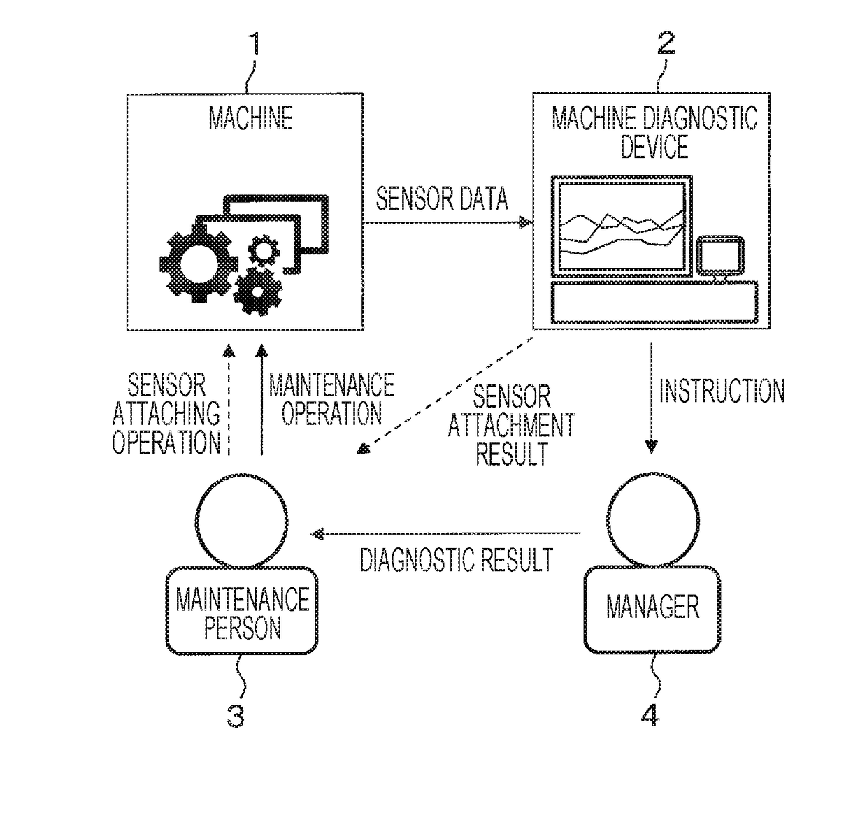
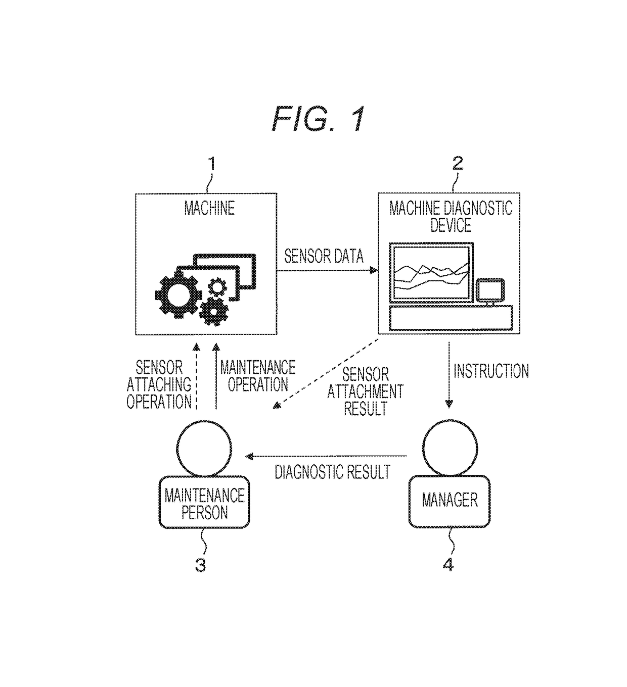
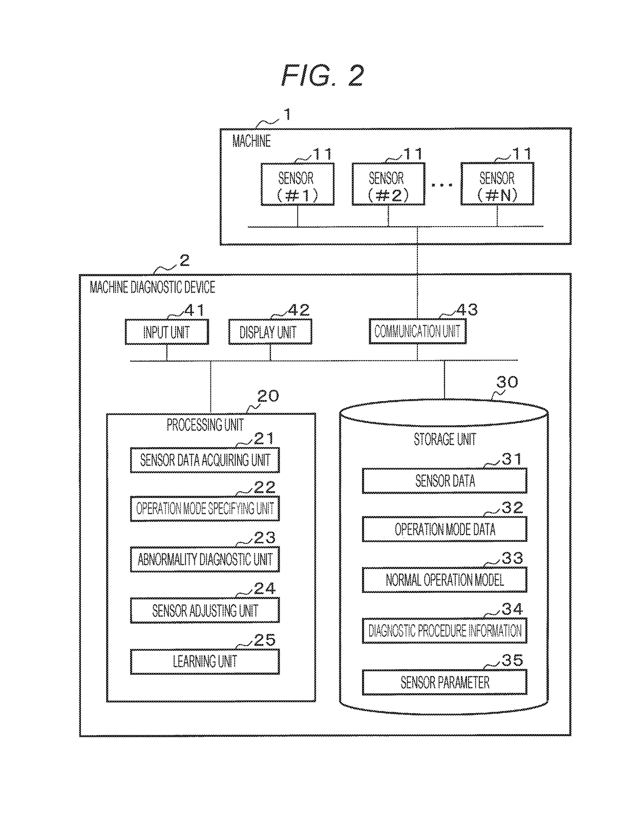
[0030]FIG. 1 is a view illustrating an example of behaviors performed by a machine 1, a machine diagnostic device 2, a maintenance person 3, and a manager 4. The machine 1 is an object device to be monitored by the machine diagnostic device 2. Maintenance of the machine 1 is periodically performed, or in a case where the machine diagnostic device 2 detects abnormality or indication of the abnormality (hereinafter, simply referred to “abnormality”), maintenance by the maintenance person 3 is performed. Various sensors 11 (refer to FIG. 2) are mounted on the machine 1, and various pieces of measurement data, which are measured by the various sensors 11, of the machine 1 are output to the machine diagnostic device 2.

[0031]The machine diagnostic device 2 collects and accumulates the various pieces of measurement data measured by the various sensors 11 from the machine 1, periodically diagnoses presence or absence of abnormality of the machine 1 in accordance with a predetermined abnorma...

embodiment 2

[0101]FIG. 14 is a flowchart illustrating an adjusting process of the sensor adjusting unit 24 according to Embodiment 2. In a case where the termination command is given from the maintenance person 3, the sensor adjusting unit 24 according to Embodiment 1 terminates a process, but there is no limitation thereto. In Embodiment 2, when the degree of abnormality is equal to or less than a threshold value set in advance during sensor adjustment, the sensor adjusting unit 24 automatically terminates a process. A processing flow of the sensor adjusting unit 24 will be described with reference to FIG. 14. In FIG. 14, the same reference numeral will be given to the same step as in FIG. 12, and description thereof will not be repeated.

[0102]In step S126, the sensor adjusting unit 24 determines whether or not the degree of abnormality (error) becomes equal to or less than a threshold value (first threshold value) that is set in advance. When the degree of abnormality becomes equal to or less...

embodiment 3

[0104]FIG. 15 is a flowchart illustrating an adjusting process of the sensor adjusting unit 24 according to Embodiment 3. In Embodiment 3, when an abnormality value becomes equal to or less than a constant value in the sensor adjustment mode, the sensor adjusting unit 24 automatically adjusts a sensor parameter 35 stored in the storage unit 30. A processing flow of the sensor adjusting unit 24 will be described with reference to FIG. 15. In FIG. 15, the same reference numeral will be given to the same step as in FIG. 12, and description thereof will not be repeated.

[0105]In step S136, the sensor adjusting unit 24 determines whether or not the degree of abnormality (error) becomes equal to or less than a threshold value (first threshold value) that is set in advance. When the degree of abnormality becomes equal to or less than the threshold value (Yes in step S136), with regard to parameters (a correction value and an offset) of an object sensor, the sensor adjusting unit 24 automati...


PUM


Abstract

The purpose of the present invention is to provide a machine diagnostic device that assists with sensor attachment such that malfunction sensing performance may be maintained even after maintenance of a device. The machine diagnostic device includes a sensor data acquisition part that acquires time-series sensor data that are measured by sensors that are attached to a machine that has one or more operating modes; a learning unit that statistically processes the sensor data prior to detachment of the sensors and computes a normal operation model; a malfunction diagnostic unit that diagnoses a malfunction of the machine on the basis of the sensor data and the normal operation model; and a sensor adjustment unit that, when the sensors are re-attached to the machine after the sensors have been detached therefrom, displays, in a display unit, as a sensor adjustment mode, discrepancies between the normal operation model prior to the detachment of the sensors and the post sensor attachment sensor data.

Description

TECHNICAL FIELD[0001]The present invention relates to a machine diagnostic device that diagnoses abnormality of a machine, and a machine diagnostic method.BACKGROUND ART[0002]Machines such as a power generation gas turbine for social infrastructure are demanded to operate for 24 hours a day. It is necessary to prevent unexpected operation stoppage to maintain high operation rate of the machines. To prevent the unexpected operation stoppage, it is necessary to switch a maintenance method from periodic maintenance of the related art based on machine operation time into state monitoring maintenance of appropriately performing preventive maintenance on the basis of a machine state.[0003]To realize the state monitoring maintenance, it is important for a machine diagnostic device to play a role of analyzing sensor data that is collected through various sensors provided to a machine according to an abnormality diagnostic procedure that is determined, and of diagnosing abnormality of the ma...

Claims


Application Information

Patent Timeline
IPC IPC(8): G05B23/02G06F15/18G06N20/00
CPCG01R31/00G01M99/005G05B23/0243G06F15/18G05B23/0283G05B23/0267G01R31/343G01M13/00G01M13/045G01M15/14G06N20/00
Inventor HIRUTA, TOMOAKIMAKI, KOHJIKATO, TETSUJIATARASHI, YOSHITAKA
Owner HITACHI LTD
Why Eureka
Try Eureka