
Electric storage cell, covering film and electric storage module

Active Publication Date: 2018-03-01
TAIYO YUDEN KK
View PDF4 Cites 1 Cited by
  • Summary
  • Abstract
  • Description
  • Claims
  • Application Information

AI Technical Summary

Benefits of technology

The present invention provides a reliable electric storage cell, covering film, and electric storage module that can safely release rising internal pressure in the event of abnormality. The slit in the external resin layer prevents corrosion of the metal layer and allows for uniform pressure release. The covering film with the aforementioned configuration can be utilized to address leakage of electrolyte from slits, improving the safety and reliability of the electric storage module at low cost.

Problems solved by technology

According to the configuration in Patent Literature 1, however, the narrow seal width at the through hole and projected fusing part may affect long-term reliability, in that moisture may permeate in through the fusing resin layer.
Besides the configuration described in Patent Literature 1, there are other configurations designed to release the internal pressure by causing a projection to break through the expanded covering film; however, they are costly because, among other reasons, a component that serves as this projection must be provided on each device.
Also, handling of such device requires attention because a projection is permanently present on it.

Method used


Image

  • Electric storage cell, covering film and electric storage module
  • Electric storage cell, covering film and electric storage module
  • Electric storage cell, covering film and electric storage module

Examples


Embodiment Construction

[0060]An embodiment of the present invention is explained below by referring to the drawings.

[0061][Structure of Electric Storage Cell]

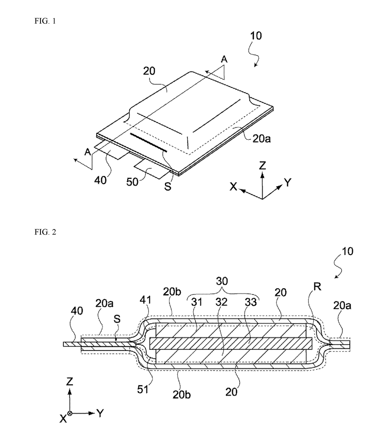
[0062]FIG. 1 is a perspective view of an electric storage cell 10 pertaining to this embodiment, while FIG. 2 is a cross sectional view of the electric storage cell 10 in FIG. 1 along line A-A. In the figures below, the X direction, Y direction and Z direction represent three directions that are orthogonal to each other.

[0063]As shown in FIGS. 1 and 2, the electric storage cell 10 has covering films 20, an electric storage element 30, a positive electrode terminal 40, and a negative electrode terminal 50.

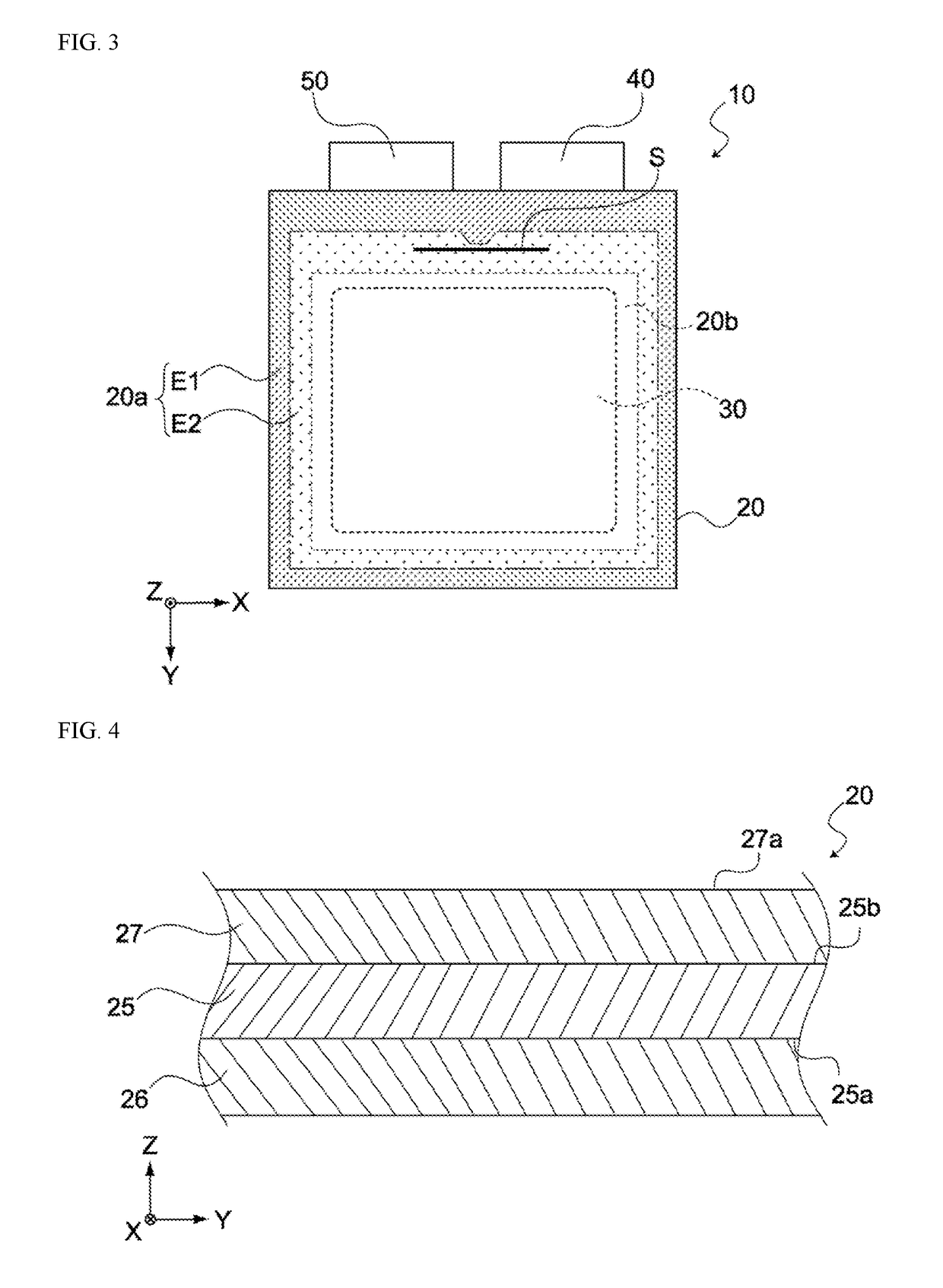
[0064]In the electric storage cell 10, the covering film package constituted by the two covering films 20 forms a housing space R, and the electric storage element 30 is housed in the housing space R. The two covering films 20 are sealed around the periphery of the electric storage element 30, and the covering film package has contact areas 20a where...


PUM

PropertyMeasurementUnit
Depthaaaaaaaaaa
Depthaaaaaaaaaa
Areaaaaaaaaaaa

Abstract

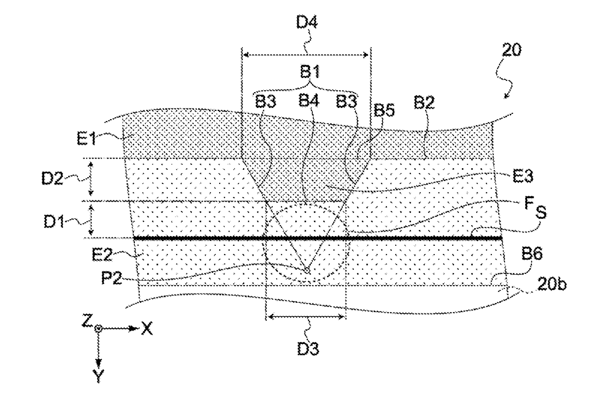
An electric storage cell has an electric storage element and a covering film package. The covering film package houses the electric storage element and includes: a metal layer having a first principle face on the electric storage element side and a second principle face on the opposite side of the first principle face, an internal resin layer laminated to the first principle face, and an external resin layer laminated to the second principle face, with a slit formed in the external resin layer; wherein the contact area further includes a non-seal area between the seal area and the electric storage element as viewed from above, wherein the seal area has a projecting area that penetrates into the non-seal area, and the slit is provided between the projecting area and the electric storage element as viewed from above.

Description

BACKGROUNDField of the Invention[0001]The present invention relates to an electric storage cell constituted by an electric storage element sealed with covering film, a covering film, and an electric storage module comprising a stack of such electric storage cells.Description of the Related Art[0002]Film-sealed batteries, which are electric storage elements sealed with covering film, are widely used in recent years. Film-sealed batteries are subject to rising pressure inside the battery due to generation of gaseous species as a result of electrolysis of the electrolyte medium, if the battery control circuit fails for some reason and abnormal voltage is applied as a result, or if the ambient temperature becomes abnormally high for some reason, while the battery is in use. As their internal pressure rises, film-sealed batteries will eventually experience a rupture of exterior material and gas will erupt from the ruptured area; however, it is not predictable where the rupture may occur,...

Claims


Application Information

Patent Timeline
IPC IPC(8): H01M2/12H01M10/0525H01M10/0566H01G11/80H01M50/119H01M50/121H01M50/129H01M50/211H01M50/55H01M50/557
CPCH01M2/1241H01M10/0525H01M2300/0025H01G11/80H01M2200/20H01M10/0566H01M10/058H01M50/129H01M50/211H01M50/55H01M50/557H01M50/119H01M50/121H01G11/12Y02E60/10H01M50/124Y02P70/50B32B27/08B32B27/32B32B27/36H01G11/78Y02E60/13H01M50/3425
Inventor NAGASHIMA, TAKAHIROYOKOSHIMA, KATSUNORITSUCHIYA, TAKAYUKISATO, HIROMIISHII, SHINJI
Owner TAIYO YUDEN KK
Learn More