Image processing apparatus, image capturing apparatus, and image processing program
a technology of image processing and image capturing, applied in the field of image processing technology, can solve problems such as ringing, image quality deterioration, and information of luminance saturation part not being correctly acquired, so as to prevent data amount from increasing and improve resolution
- Summary
- Abstract
- Description
- Claims
- Application Information
AI Technical Summary
Benefits of technology
Problems solved by technology
Method used
Image
Examples
example 1
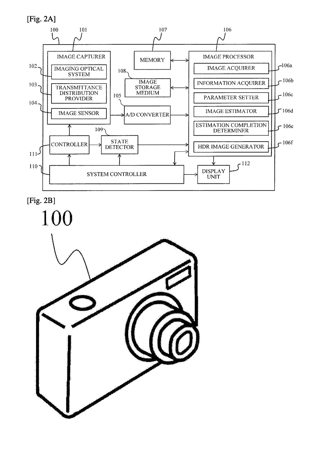
[0045]FIGS. 2A and 2B illustrate a configuration and an overview of an image capturing apparatus 100 that includes an image processing apparatus according to the first embodiment. This embodiment characteristically provides, through a space division, different transmittance distributions corresponding to light intensity distributions with a plurality of exposures.
[0046]Light from the object space enters an image capturer 101. The image capturer 101 includes an imaging optical system 102 configured to form an optical image (object space image) by condensing the light from the object space, a transmittance distribution provider 103, and an image sensor 104 in which a plurality of pixels are arranged. The image sensor 104 is a photoelectric conversion element, such as a CCD sensor and a CMOS sensor. The transmittance distribution provider 103 will be described in detail later.
[0047]The light (object space image) that has passed the imaging optical system 102 before image capturing is r...
example 2
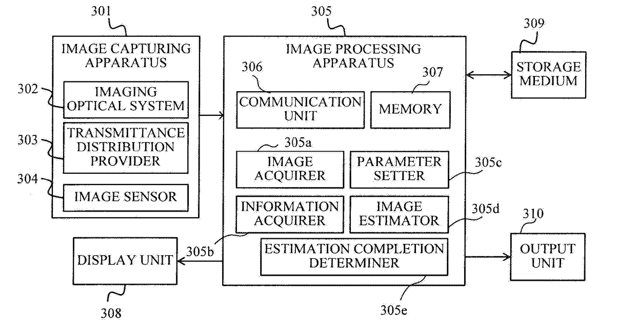
[0130]A description will be given of an image processing system according to a second embodiment of the present invention. This embodiment uses different transmittance distributions provided to a plurality of exposures using the time division. This embodiment includes an image capturing apparatus and an image processing apparatus as separate apparatuses.
[0131]FIG. 7A illustrates a configuration of the image processing system according to this embodiment, and FIG. 7B illustrates its overview. An image capturing apparatus 301 includes an imaging optical system 302 configured to condense light from an object space, and to form an optical image (object space image), a transmittance distribution provider 303, and an image sensor 304 in which a plurality of pixels are arranged. The image sensor 304 is a photoelectric conversion element, such as a CCD sensor and a CMOS sensor. A description will be given later of a method for acquiring a captured image (input image) by the image capturing ...
example 3
[0144]A description will be given of an image processing system according to a third embodiment of the present invention. This embodiment makes different transmittance disributions provided to a plurality of exposures using time divisions similar to the second embodiment, but this embodiment is different from the second embodiment in that this embodiment provides the transmittance distribution to each exposure after the light intensity distribution with each exposure is obtained by the image sensor.
[0145]FIG. 11A illustrates a configuration of the image processing system according to this embodiment, and FIG. 11B illustrates its overview. A server 406 as the image processing apparatus includes a communication unit 407, and is connected to an image capturing apparatus 401 via a network 405. This connection may be a wire connection or a wireless connection.
[0146]The image capturing apparatus 401 includes an imaging optical system 402 configured to condense light from the object space,...
PUM
 Abstract
Description
Claims
Application Information
 - R&D
- Intellectual Property
- Life Sciences
- Materials
- Tech Scout
- Unparalleled Data Quality
- Higher Quality Content
- 60% Fewer Hallucinations
Browse by: Latest US Patents, China's latest patents, Technical Efficacy Thesaurus, Application Domain, Technology Topic, Popular Technical Reports.
© 2025 PatSnap. All rights reserved.Legal|Privacy policy|Modern Slavery Act Transparency Statement|Sitemap|About US| Contact US: help@patsnap.com


