Solid state cooling device

a solid-state cooling and cooling device technology, applied in the field of cooling devices, can solve the problems of poor efficiency of current tec technologies, adverse environmental impact, and the development of magnetic coolers that can span a large temperature range, so as to increase reduce the magnetic field force, and increase the magnetic field.

Active Publication Date: 2018-03-08
RGT UNIV OF CALIFORNIA +1
View PDF0 Cites 12 Cited by
  • Summary
  • Abstract
  • Description
  • Claims
  • Application Information

AI Technical Summary

Benefits of technology

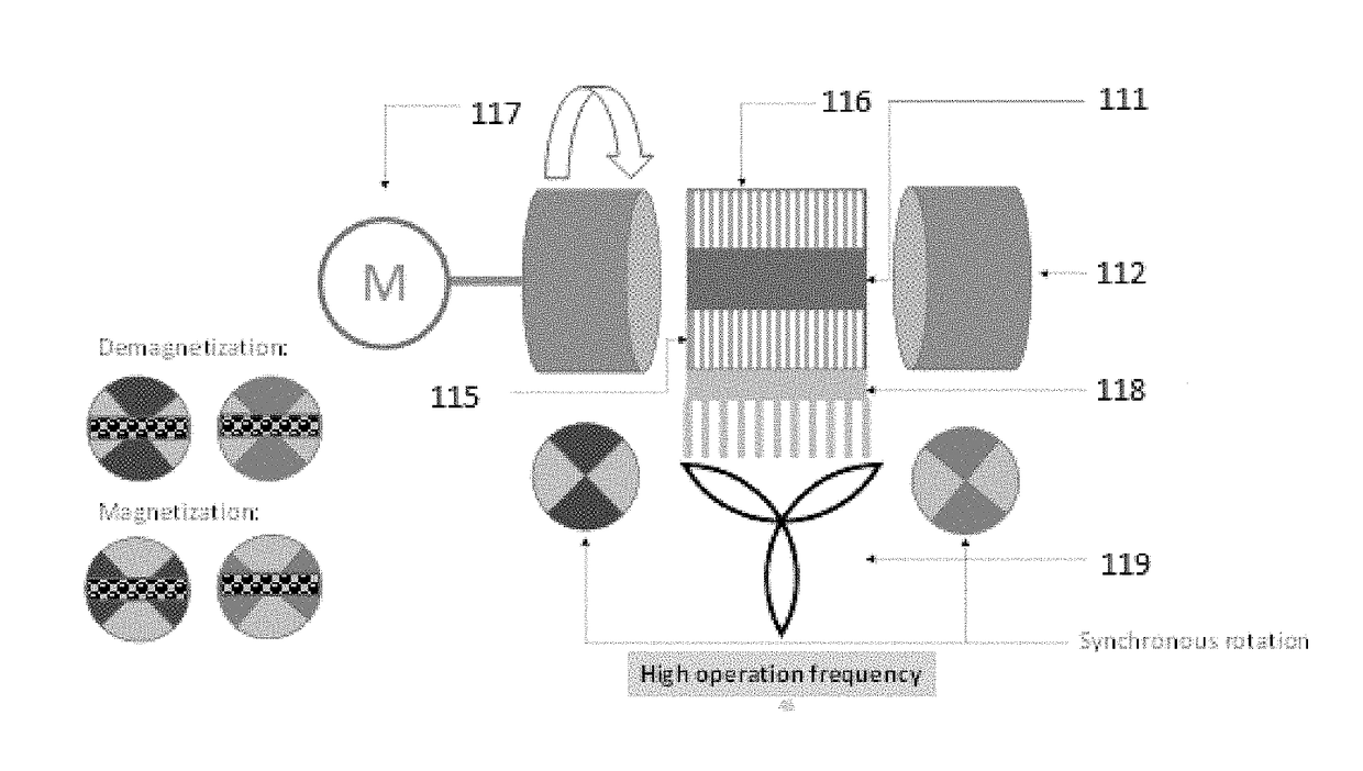
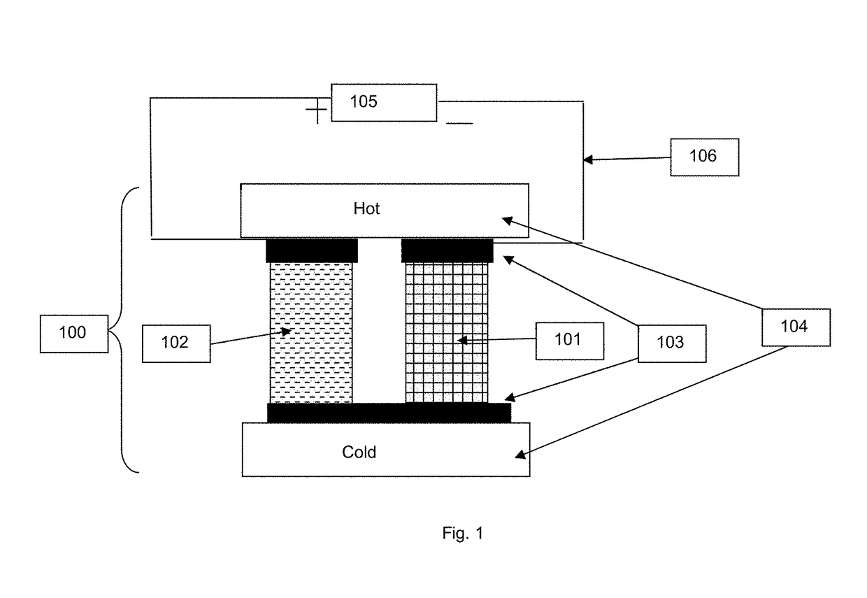
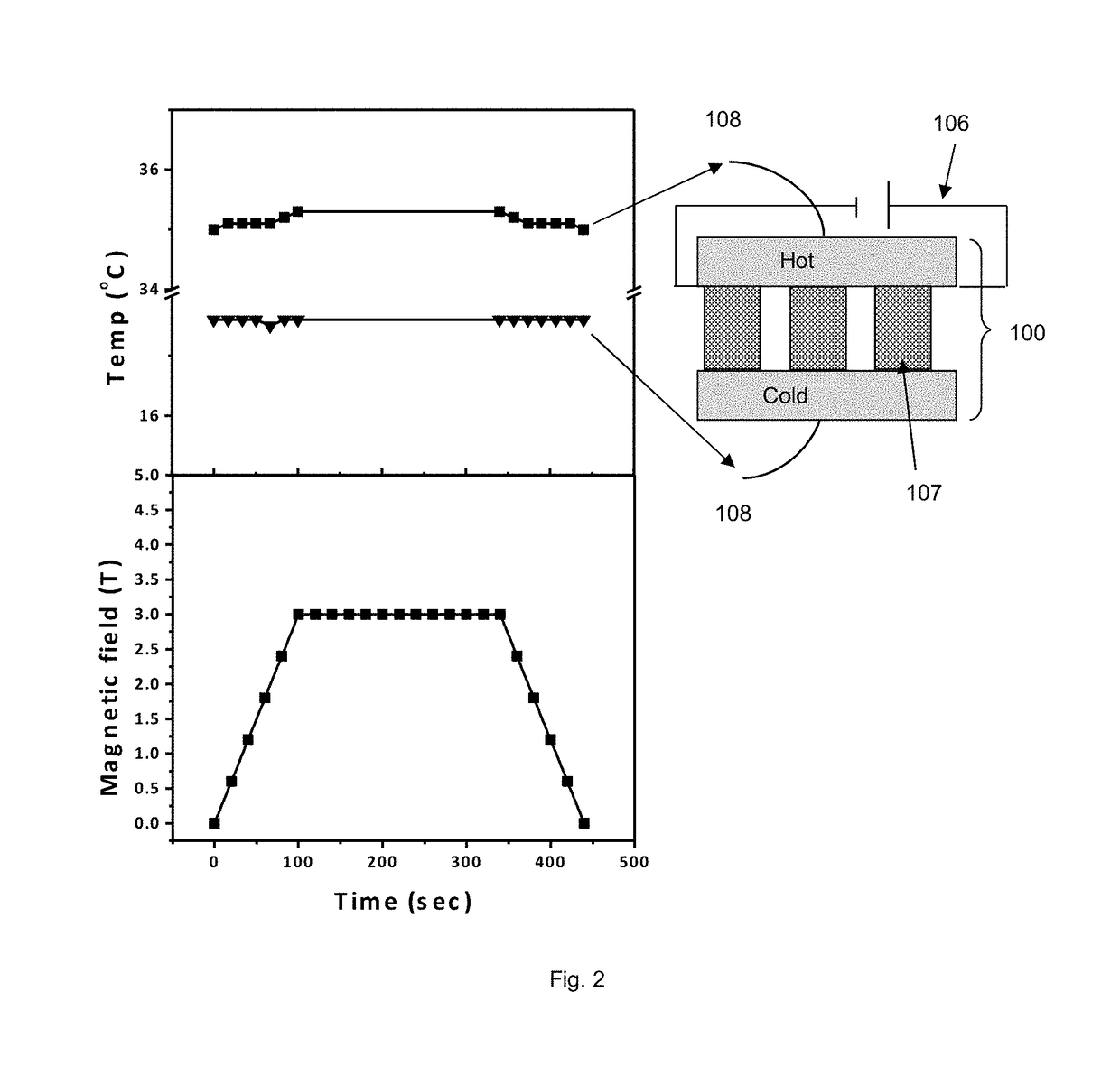
[0009]Some embodiments of the present invention provide a cooling device comprising a hot side, a cold side, at least two thermoelectric layers, at least one magnetocaloric composite, and a magnetic field. In some embodiments, the at least one magnetocaloric composite is positioned in between the at least two thermoelectric layers. In some embodiments, the at least one magnetocaloric composite comprises at least one magnetocaloric material and at least one thermally conductive material with thermal conductivity greater than 75 W / (m K) at the operating temperature of the cooling device, wherein the magnetocaloric material and the thermally conductive material are not the same. In some embodiments, the magnetic field enables the magnetocaloric effect of the magnetocaloric material in the magnetocaloric composite when at least one magnetization and demagnetization cycle is performed, wherein a change in temperature of the magnetocaloric material occurs when the magnetocaloric material is exposed to changes in magnetic field force. In some embodiments, the at least one magnetization and demagnetization cycle comprises increasing the magnetic field force on the magnetocaloric material at a predefined magnetic field ramp-up speed, maintaining the increased magnetic field on the magnetocaloric material for a specified holding time, decreasing the magnetic field force on the magnetocaloric material at a predefined ramp-down speed, and maintaining the decreased magnetic field on the magnetocaloric material for a specified time. In some embodiments, the at least two thermoelectric layers operate separately to move heat from the cold side of the device to the hot side of the device when a DC current is applied in a specified direction, wherein the DC current applied to each thermoelectric layer is electrically coupled to the magnetization and demagnetization cycle of the magnetocaloric material such that one thermoelectric layer operates to allow heat rejection from the magnetocaloric composite to the hot side and one thermoelectric layer operates to allow heat absorption to the magnetocaloric composite from the cold side.

Problems solved by technology

Most conventional air conditioners, heat pumps, and refrigerators achieve cooling through a mechanical vapor compression cycle (VCC) which requires large amounts of energy and has an adverse environmental impact due to the use of hydrofluorocarbons (HFCs).
However, the drawback of current TEC technologies is their poor efficiency.
However, the MCE materials must operate in a predetermined temperature range and development of magnetic coolers that can span a large temperature range has, to this point, been unsuccessful.
However, their theoretical device requires a non-existant insulative material whose thermal conductivity changes with application of a magnetic field.

Method used


Image

  • Solid state cooling device
  • Solid state cooling device
  • Solid state cooling device

Examples


example 2

[0093]FIG. 9 shows the temperature versus time of an embodiment of the invention where the solid state cooling module uses a magnetocaloric composite comprising a magnetocaloric material 113 and a thermally conductive material 114. The module was constructed similar to Comparative Example 1, except the Gd plates 113 were each wrapped with Copper foil 114 and adhered in between the thermoelectric modules.

[0094]FIG. 9 shows the temperature versus time for the device where the figure on the left shows the stabilized temperature fluctuation of the cold side without the magnetic field. The thermoelectric modules are cycled off and on every 8 seconds, causing the cold side temperature to fluctuate from 20.1 C to 21.7 C. When the magnetization and demagnetization cycle is performed on the device using the same procedure as described in Comparative Example 1, the cold side temperature decreases, and fluctuates between 19.7 C and 21.4 C. This shows cooling occurring due to the magnetocaloric...

example 3

[0095]FIG. 10 shows the temperature versus time of the same solid state cooling module of Example 2, except the cycle time is every 10 seconds. The stabilized cold side temperature fluctuates from 21.3 C to 23.3 C. When the magnetization and demagnetization cycle is performed on the device using the same procedure as described in Comparative Example 1, the cold side temperature decreases, and fluctuates between 20.9 C and 23.1 C. This shows cooling occurring due to the magnetocaloric effect, which is made possible only by using the magnetocaloric composite structure as disclosed herein.

example 4

[0096]FIG. 11 shows the temperature versus time of the same solid state cooling module of Example 2, except the cycle time is every 12 seconds. The stabilized cold side temperature fluctuates from 19.7 C to 21.8 C. When the magnetization and demagnetization cycle is performed on the device using the same procedure as described in Comparative Example 1, the cold side temperature decreases, and fluctuates between 19.3 C and 21.5 C. This shows cooling occurring due to the magnetocaloric effect, which is made possible only by using the magnetocaloric composite structure as disclosed herein.


PUM

PropertyMeasurementUnit
thermal conductivityaaaaaaaaaa
thicknessaaaaaaaaaa
thicknessaaaaaaaaaa

Abstract

This invention relates to a cooling device which utilizes both thermoelectric and magnetocaloric mechanisms for enhanced cooling applications. Using high thermal conductivity magnetocaloric composites in conjunction with thermoelectric elements acting as thermal switches which are electrically coupled to a magnetization and demagnetization cycle enables the use of larger quantities of magnetocaloric material, and high efficiency solid state cooling can be achieved. Solid state cooling devices are useful for a variety of industrial applications which require cooling, such as, but not limited to cooling of microelectronic devices, cooling on space platforms, etc.

Description

CROSS-REFERENCE TO RELATED APPLICATIONS[0001]This application claims priority to U.S. Provisional Patent Application No. 62 / 383,363 filed on Sep. 2, 2016 entitled “SOLID STATE COOLING DEVICE”, the content of which is incorporated herein by reference in its entirety.STATEMENT REGARDING FEDERALLY SPONSORED R&D[0002]This invention was made with government support under grant No. N00173141G016 awarded by the Naval Research Laboratory. The government has certain rights in the invention.BACKGROUND OF THE INVENTIONField of the Invention[0003]Embodiments of the present invention generally relate to a cooling device which utilizes both thermoelectric and magnetocaloric mechanisms for enhanced cooling applications. Using high thermal conductivity magnetocaloric composites in conjunction with thermoelectric elements acting as thermal switches which are electrically coupled to a magnetization and demagnetization cycle enables the use of effective quantities of magnetocaloric material, and high ...

Claims


Application Information

Patent Timeline
Patent Type & Authority Applications(United States)
IPC IPC(8): F25B21/00H01L35/32H01L37/04
CPCF25B21/00H01L35/32H01L37/04H01L35/14F25B2321/002Y02B30/00H10N10/851H10N15/20H10N10/17
Inventor IHNFELDT, ROBIN VERONICAXU, XIACHEN, RENKUNJIN, SUNGHOZHENG, JIANLIN
Owner RGT UNIV OF CALIFORNIA
Why Eureka
Try Eureka