Incident-light illumination for a variable working distance

a working distance and incident light technology, applied in semiconductor devices, lighting and heating apparatus, instruments, etc., can solve the problems of only being usable for a specific application, large volume, and heavy weight of front optical units, and achieve the effect of simple change provision and cost-effectiveness

Active Publication Date: 2018-03-08
CARL ZEISS IND MESSTECHN GMBH
View PDF5 Cites 12 Cited by
  • Summary
  • Abstract
  • Description
  • Claims
  • Application Information

AI Technical Summary

Benefits of technology

[0021]However, using the proposed lens device renders it possible to modify the angle of incidence or the inclination angle of the light-exit surface in relation to the light-entry surface in the direction of the central axis. This is carried out by virtue of the lens device being rotated about the central axis. By way of example, an illumination arrangement can be assigned to each area segment. Then, in a first position, the relative arrangement of the lens device or of a respective area segment in relation to the illumination arrangement may be such that it is substantially the first angle that is effective. Rotating the lens device about the central axis then causes the second angle, which is different from the first angle, to substantially be effective in a second position. In this way, it is possible to illuminate at least two working distances or alternate between various working distances.
[0063]In this way, the method is provided with a lens device in accordance with the first aspect, facilitating a cost-effective and simple implementation of the method.

Problems solved by technology

However, such a front optical unit is relatively heavy on account of the optical elements for imaging purposes and has a relatively large volume.
Moreover, such a front optical unit is only usable for a specific application, i.e. at a specific working distance and for a specific illumination type.
However, this also results in a relatively complex structure of such illumination elements and, possibly, a relatively high weight and volume which makes regulating the optical sensor head more difficult on account of the higher inertia connected therewith, in particular in the case of fast measuring processes.
However, such arrangements make an illumination assembly heavier on the one hand and, on the other hand, increase the costs of an illumination assembly.

Method used


Image

  • Incident-light illumination for a variable working distance
  • Incident-light illumination for a variable working distance
  • Incident-light illumination for a variable working distance

Examples


Embodiment Construction

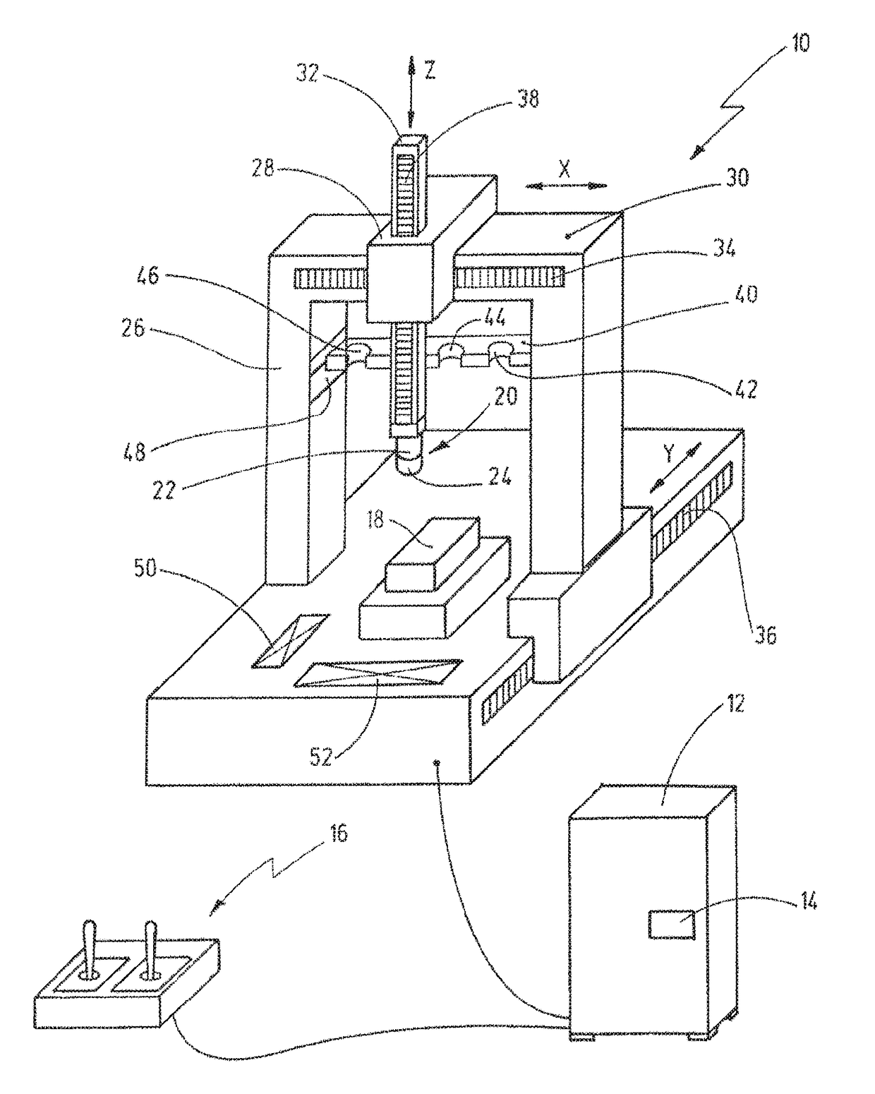
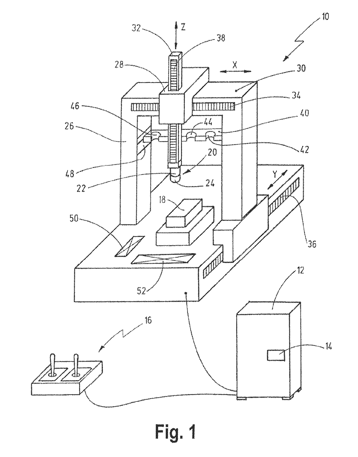
[0084]FIG. 1 shows an embodiment of a coordinate measuring machine 10. The coordinate measuring machine 10 comprises a regulating device 12 which is embodied to control the coordinate measuring machine 10 in an automated manner. To this end, the regulating device 12 may comprise a data processing unit 14. Moreover, the regulating device 12 may also comprise indication apparatuses which indicate information items about selected modes of operation, measurement results, etc. to a user of the coordinate measuring machine 10. Moreover, the coordinate measuring machine 10 comprises an operating device 16 which allows a user to control the coordinate measuring machine 10. Here, the operating device 16 is only depicted schematically. On the one hand, this should facilitate manual movement of the coordinate measuring machine 10. Moreover, the operating device 16 may be embodied to allow the user to enter system inputs into the regulating device 12 in order to select a mode of operation, etc....


PUM


Abstract

A lens device for an illumination assembly. The lens device has light-entry and light-exit surfaces and comprises at least one ring region. Each ring region extends along a circumferential direction about a central axis of the lens device, and comprises a plurality of area segments. Each area segment forms a circular arc portion of a respective ring region and comprises a first end in the circumferential direction and a second end opposite to the first end in the circumferential direction. At the first end, the light-exit surface is inclined in the direction of the central axis by an arbitrary first angle in relation to the light-entry surface, and at the second end, the light-exit surface is inclined in the direction of the central axis by an arbitrary second angle in relation to the light-entry surface differing from the first angle.

Description

CROSS-REFERENCE TO RELATED APPLICATIONS[0001]This is a Continuation application of International patent application PCT / EP2016 / 057497, filed Apr. 6, 2016, which claims the priority of German patent application DE 10 2015 105 613.5, filed Apr. 13, 2015. The entire content of both applications is herewith incorporated by reference.BACKGROUND OF THE INVENTION[0002]The present invention relates to a lens device for an illumination assembly. Moreover, the present invention relates to an illumination assembly for a measuring machine for measuring a workpiece by means of an optical sensor. Moreover, the present invention relates to a coordinate measuring machine for measuring a workpiece by means of an optical sensor. Moreover, the present invention relates to a method for modifying an illumination working distance of a dark field top light illumination of a coordinate measuring machine.[0003]Coordinate measuring machines are used to check workpieces, for example as part of quality assuran...

Claims


Application Information

Patent Timeline
Patent Type & Authority Applications(United States)
IPC IPC(8): G01B11/00F21V8/00F21V5/04F21V14/06
CPCG01B11/005G02B6/0001F21V5/04F21V14/06F21Y2115/10G02B3/0037
Inventor SEITZ, DOMINIKHAVERKAMP, NILS
Owner CARL ZEISS IND MESSTECHN GMBH
Why Eureka
Try Eureka