Mechanical High Spin-Shock Testing Machines

a testing machine and spin-shock technology, applied in the field of spin-shock testing machines, can solve the problems of prohibitively high cost of engineering development of such components and their reliability testing, which requires testing of a large number of samples, and achieve the effect of short tim

Active Publication Date: 2018-03-08
OMNITEK PARTNERS LLC
View PDF11 Cites 9 Cited by
  • Summary
  • Abstract
  • Description
  • Claims
  • Application Information

AI Technical Summary

Benefits of technology

[0022]A need also exists for novel mechanical rotary shock testing machines that can provide the means of testing a large number of fully instrumented components in a relatively short time. This requires that the said mechanical shock testing machine allows rapid mounting of test components onto the test platform while allowing relatively free access to the said components, unlike the “piston” platforms used in air guns (aforementioned method “7”) or inside projectiles that are gun-launched (aforementioned method “9”).

Problems solved by technology

A need also exists for methods that are not be based on the use of the actual or similar platforms, for example, firing projectiles carrying the test components with similar guns such as the described in the method “9” above, due to the cost and difficulty in providing full instrumentation which would allow testing of a few components at a time, thereby making the cost of engineering development of such components and their reliability testing which requires testing of a large number of samples prohibitively high.

Method used


Image

  • Mechanical High Spin-Shock Testing Machines
  • Mechanical High Spin-Shock Testing Machines
  • Mechanical High Spin-Shock Testing Machines

Examples


embodiment 10

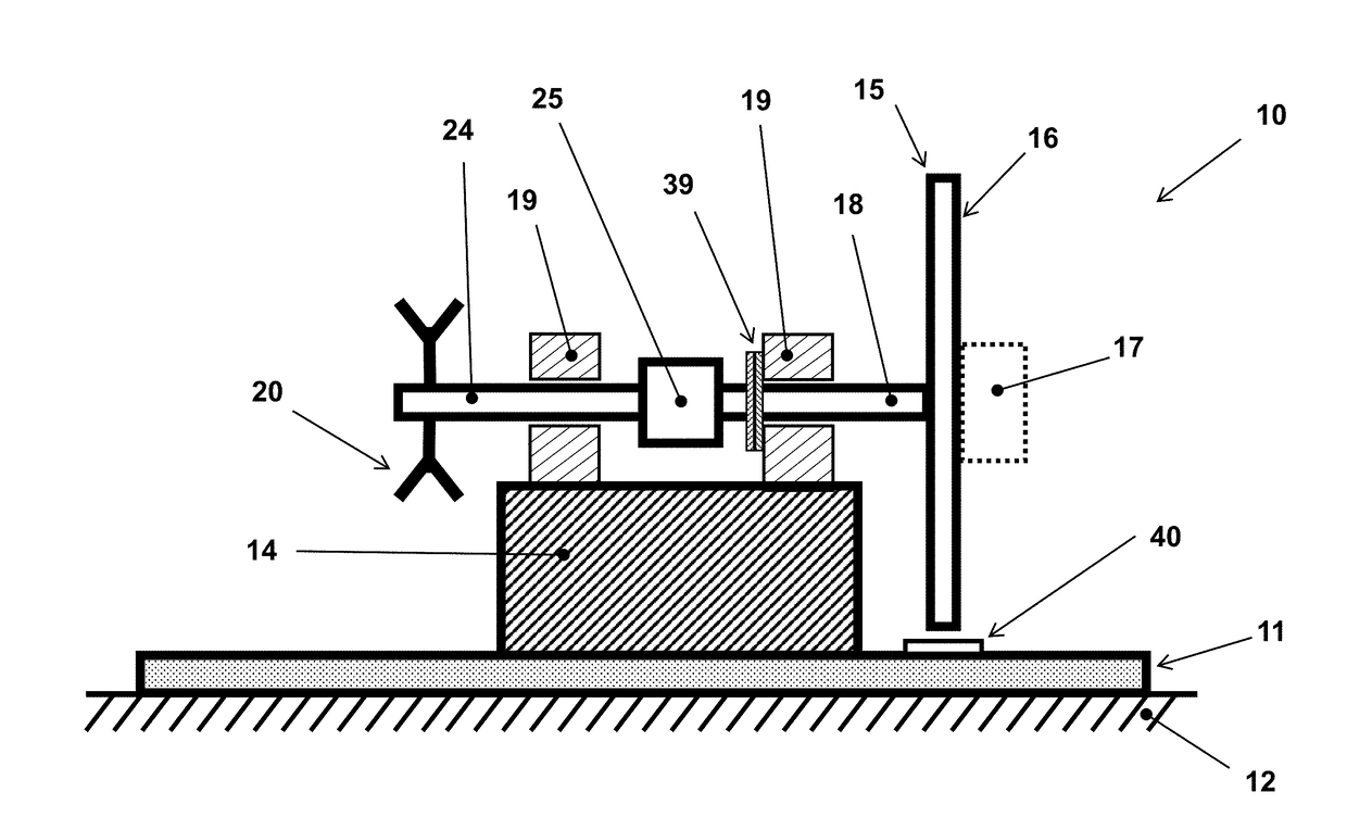
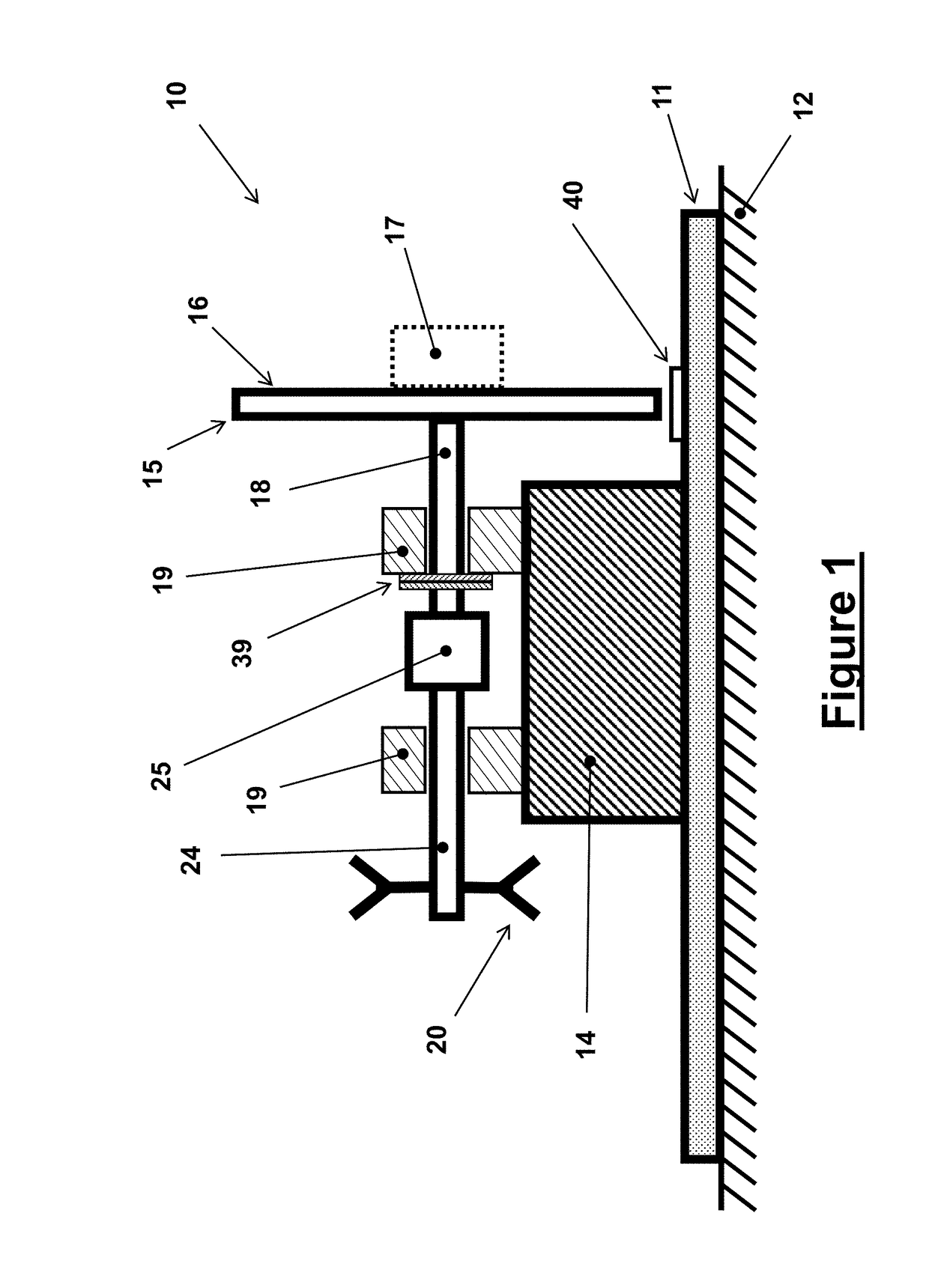
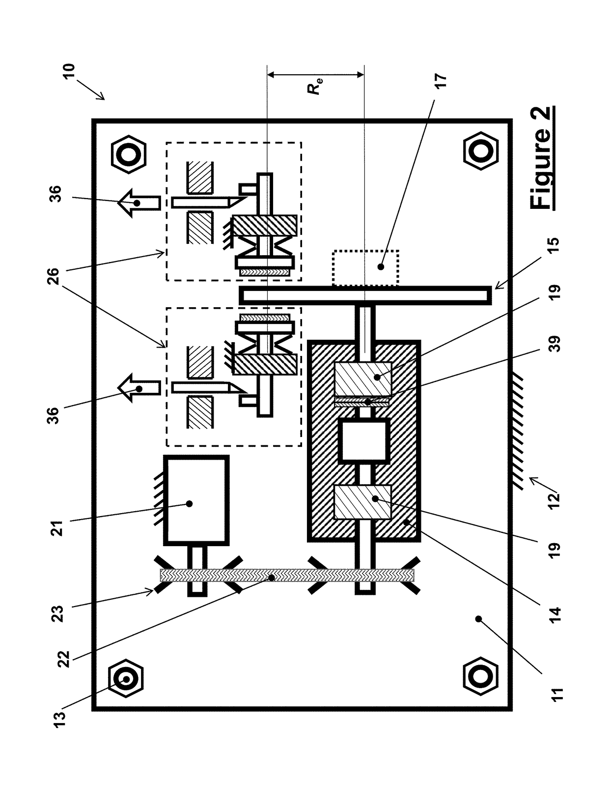
[0034]The basic design and operation of the mechanical rotary shock-testing machine is shown in the schematic of FIG. 1 and is indicated as the embodiment 10. The mechanical rotary shock testing machine 10 is constructed over a base plate 11, which can be made out of a heavy and thick steel plate which is firmly anchored to the machine foundation 12 by at least four heavy anchoring bolts (13 in FIG. 2) that are far enough apart around the base plate to resist the high torque reaction pulses (shocks) in reaction to the rotary shock loading pulses generated by the mechanical rotary shock testing machine 10. The top view of this embodiment 10 of the mechanical rotary shock testing machine is shown in FIG. 2. Certain relatively stiff shock absorbing elements (not shown) may be provided between the base 11 and the foundation 12 to prevent damage to the foundation structure. In heavier machinery, a relatively large (usually made out of reinforced concrete) foundation block (not shown) can...

embodiment 50

[0057]The braking units 26 shown in the schematic of FIG. 3 are designed to apply braking force to one or the other surface of the testing platform disc 15 or independently to both sides of the said disc as shown in FIG. 2. The braking units 26 similarly applies braking forces to one or independently to both sides of the disc brakes 43 of the mechanical rotary shock testing machine embodiment 50 shown in the schematic FIG. 5. It will be, however, appreciated by those skilled in the art that the best method of applying braking forces to a rotating disc is by applying equal but opposite forces to the sides of the disc and with the resultant force being as collinear as possible so that they would not subject the disc to a bending moment. As a result, the braking disc can be relatively thin, thereby reducing the overall system moment of inertia and the decelerating friction generated torque needed to apply a prescribed deceleration rate to the components being tested 17. In addition, th...


PUM

PropertyMeasurementUnit
braking forceaaaaaaaaaa
velocityaaaaaaaaaa
accelerationaaaaaaaaaa

Abstract

A rotary shock testing machine including: a base; a shaft rotatable relative to the base; a test disc for holding one or more specimens to be tested, the test disc being rotatable with the shaft; an actuator for applying a rotation to the shaft and test disc; and a brake for applying a braking force to the test disc to subject the one or more specimens to a rotary shock.

Description

BACKGROUND OF THE INVENTION1. Field of the Invention[0001]The present invention relates generally to a spin-shock testing machine for subjecting the components to be tested to a rotary acceleration pulse of a prescribed amplitude and duration, and more particularly for testing various devices and components of rifled gun-fired munitions as well said munitions by subjecting them to similar launch spin acceleration pulses generated by the gun barrel rifling.2. Prior Art[0002]Munitions fired from guns with rifled barrels are subjected to high rotary acceleration pulse as they are accelerated in rotation to their muzzle exit spin rates, generally to achieve highly stabilized flight. Spin deceleration is also encountered as munitions impact the target. As a result, all components of the munitions and the assembled munitions itself must survive the said shock loading event due to the imparted high rotary acceleration pulse and be qualified to such severe environments.[0003]Component testi...

Claims


Application Information

Patent Timeline
Patent Type & Authority Applications(United States)
IPC IPC(8): G01N3/307G01N3/31F42B35/00F42B30/02
CPCG01N3/307G01N3/31F42B35/00G01N2203/0204G01N2203/0035G01N2203/0042G01N2203/0647F42B30/02
Inventor RASTEGAR, JAHANGIR S.
Owner OMNITEK PARTNERS LLC
Why Eureka
Try Eureka