Plenoptic imaging device equipped with an enhanced optical system

Active Publication Date: 2018-03-08
INTERDIGITAL CE PATENT HLDG
View PDF0 Cites 20 Cited by
  • Summary
  • Abstract
  • Description
  • Claims
  • Application Information

AI Technical Summary

Benefits of technology

The invention captures a wider field of view by rotating multiple camera lenses to capture a portion of the scene with reduced or without optical aberration. This allows for a higher quality composite image to be formed by combining the multiple decentred images. The use of facets oriented in a certain way makes it possible to capture all the necessary rotated fields of view for a good quality image. This improves the quality of images captured using a plenoptic device.

Problems solved by technology

Depth, for example, is lost during the acquisition.
Thus, a conventional capture device does not store most of the information about the light distribution from the scene.
Conventional optical systems possess inherent aberrations that degrade the quality of images formed by the optical system and acquired by the photosensor.
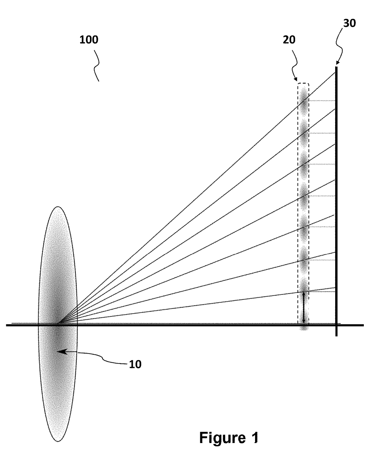
This shows that the main-lens 110 inherently suffers optical aberrations in peripheral regions that affect the image quality particularly at the edges of the image, resulting a lack of acutance at these areas of image.

Method used


Image

  • Plenoptic imaging device equipped with an enhanced optical system
  • Plenoptic imaging device equipped with an enhanced optical system
  • Plenoptic imaging device equipped with an enhanced optical system

Examples


Embodiment Construction

[0049]In all of the figures of the present document, identical elements are designated by the same numerical reference sign.

[0050]As it will be described more fully hereafter with reference to the accompanying figures, it is proposed in one aspect of the present disclosure to capture an expanded field-of-view of a scene using a plenoptic imaging device, to improve quality of the image captured. This disclosure may, however, be embodied in many alternate forms and should not be construed as limited to the embodiments set forth herein. Accordingly, while the disclosure is susceptible to various modifications and alternative forms, specific embodiments thereof are shown by way of example in the drawings and will herein be described in detail. It should be understood, however, that there is no intent to limit the disclosure to the particular forms disclosed, but on the contrary, the disclosure is to cover all modifications, equivalents, and alternatives falling within the spirit and sco...


PUM


Abstract

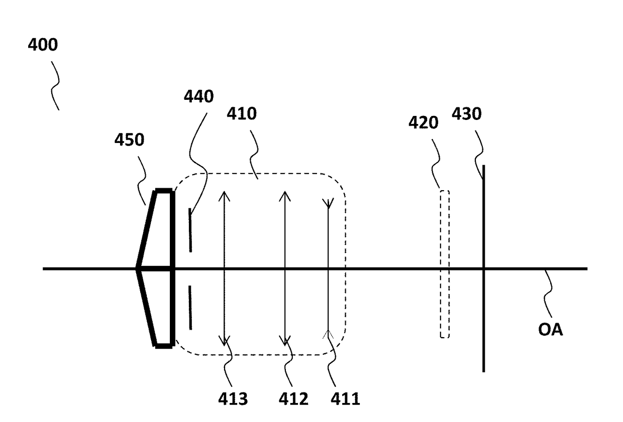
A plenoptic imaging device is described including a micro-lens array placed between a main lens and a photosensor. The micro-lens array has a plurality of micro-lenses each configured to project a micro-image onto the photosensor, the main lens covering a central field-of-view of the scene according to capture axis. The plenoptic imaging device includes multi-faceted optical means structure having at least two facets and placed in a plane adjacent to the aperture diaphragm plane and centered on the main optical axis, each facet being configured to angularly rotated the capture axis with respect to the main optical axis so as to capture a rotated field-of-view from the central field-of-view, and so that the captured rotated field-of-views form an expanded field-of-view covering the central field-of-view.

Description

1. REFERENCE TO RELATED EUROPEAN APPLICATION[0001]This application claims priority from European Patent Application No. 16306119.5, entitled “PLENOPTIC IMAGING DEVICE EQUIPPED WITH AN ENHANCED OPTICAL SYSTEM,” filed on Sep. 7, 2016, the contents of which are hereby incorporated by reference in its entirety.2. TECHNICAL FIELD[0002]The present disclosure relates to light-field imaging. More particularly, the disclosure pertains to technologies for acquiring and processing light-field data. More specifically, the present disclosure relates to plenoptic imaging device design.3. BACKGROUND[0003]The present section is intended to introduce the reader to various aspects of art, which may be related to various aspects of the present invention that are described and / or claimed below. This discussion is believed to be helpful in providing the reader with background information to facilitate a better understanding of the various aspects of the present invention. Accordingly, it should be under...

Claims


Application Information

Patent Timeline
IPC IPC(8): G02B3/00H04N13/02H04N5/225G02B27/00G02B13/00H04N13/232
CPCG02B3/0056H04N13/0232H04N5/2254G02B3/0075G02B27/0075G02B13/0015G02B13/0055H04N13/232H04N23/58G06T7/557H04N23/957
Inventor VANDAME, BENOITBABON, FREDERICDRAZIC, VALTER
Owner INTERDIGITAL CE PATENT HLDG
Why Eureka
Try Eureka