Optical fiber splice element

a technology of optical fiber and splice element, which is applied in the field of optical fiber splice element, can solve the problems of slack storage, high optical loss 0.2 db-0.3 db, and slack storage, and leave unsightly and bulky excess fiber coils

Inactive Publication Date: 2018-03-08
3M INNOVATIVE PROPERTIES CO
View PDF14 Cites 24 Cited by
  • Summary
  • Abstract
  • Description
  • Claims
  • Application Information

AI Technical Summary

Problems solved by technology

Ferrule type connectors offer test access sites, but have the drawback of higher optical loss 0.2 dB-0.3 dB, space, and require cleaning before every mate.
If factory terminated, they require slack storage, due to their being purchased in standard units, leaving unsightly and bulky excess fiber coils.
The machines are expensive, $3000 to $10,000, sensitive instruments which are easily damaged.
It is not economically feasible to purchase and train craft so that every FTTH installer has a machine.
They offer insertion loss which is better than connectors, but poorer than fusion.
The gels do not perfectly match the index of refraction of silica at the temperature extremes.
This causes reflection from the joint which does not meet some telecommunication standards.
In addition, the gel utilized is not a solid material, and therefore has no structural integrity.

Method used


Image

  • Optical fiber splice element
  • Optical fiber splice element
  • Optical fiber splice element

Examples


embodiments

[0294]Various embodiments are provided.

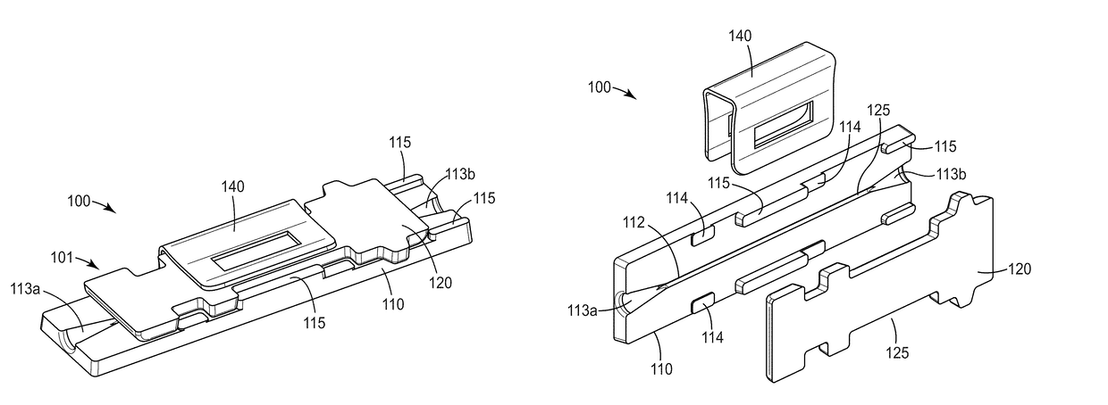
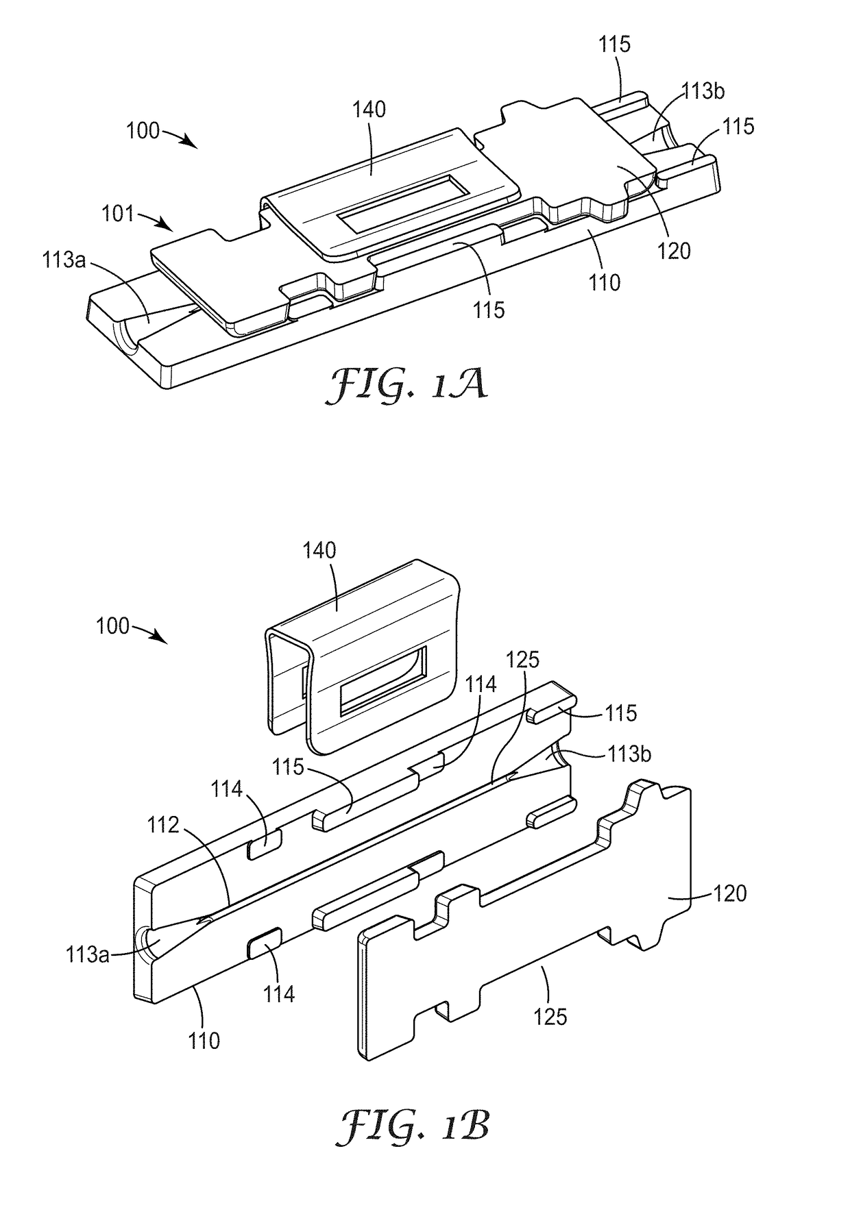
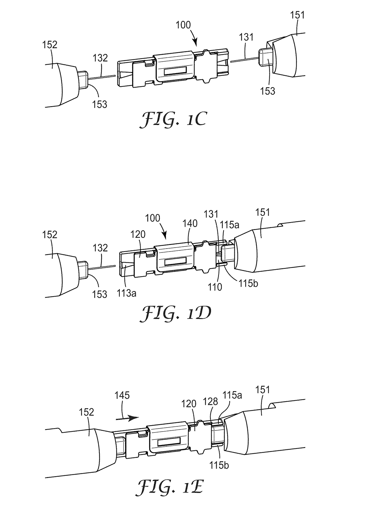
[0295]Embodiment 1A is a splice element for splicing a first and a second optical fiber, comprising an alignment mechanism having a base plate and a clamp plate, at least one of the base plate and clamp plate being formed from a silica material, and at least one of the base plate and clamp plate having an alignment groove configured to receive the first and second optical fibers in an end-to-end manner; and an optical adhesive disposed in at least a portion of the alignment groove, wherein the optical adhesive is curable via actinic radiation.

[0296]Embodiment 2A is the splice element of embodiment 1A, wherein the optical adhesive is blue light curable.

[0297]Embodiment 3A is the splice element of any preceding embodiment, wherein the optical adhesive comprises an adhesive composition containing non-aggregated, surface-modified silica nano-particles dispersed in an epoxy resin.

[0298]Embodiment 4A is the splice element of any preceding embodiment,...


PUM


Abstract

A splice element for splicing a first and a second optical fiber comprises an alignment mechanism having a base plate and a clamp plate. At least one of the base plate and clamp plate is formed from a silica material and at least one of the base plate and clamp plate includes an alignment groove configured to receive the first and second optical fibers in an end-to-end manner. The splice element also comprises an optical adhesive disposed in at least a portion of the alignment groove, wherein the optical adhesive is curable via actinic radiation.

Description

BACKGROUNDField of the Invention[0001]The present invention is directed to a splice element for splicing a first and a second optical fiber.Related Art[0002]Communications service providers are faced with increasing demands to deliver faster and better service to their customers. Service providers can meet these needs for greater bandwidth by incorporating fiber optics in the access network, the communication connection to the end subscriber. Service providers have announced gigabit service offerings.[0003]Ferrule type connectors offer test access sites, but have the drawback of higher optical loss 0.2 dB-0.3 dB, space, and require cleaning before every mate. If factory terminated, they require slack storage, due to their being purchased in standard units, leaving unsightly and bulky excess fiber coils.[0004]Fusion machines create low loss permanent reliable, splices. The machines are expensive, $3000 to $10,000, sensitive instruments which are easily damaged. It is not economically...

Claims


Application Information

Patent Timeline
Patent Type & Authority Applications(United States)
IPC IPC(8): G02B6/255
CPCG02B6/2553G02B6/2555G02B6/2556G02B6/2557G02B6/2558G02F2202/28C09J11/00B01J21/08B01J35/023B01J35/1014B01J35/1019B01J35/1023C04B26/14G02B6/3885C04B2111/80G02B6/255C04B14/062C04B40/0222C09J2301/416C09J11/04C09J163/00
Inventor LARSON, DONALD K.CLATANOFF, WILLIAM J.TREADWELL, DANIEL J.ALLEN, WILLIAM G.SELLI, RAMAN K.HUMPAL, KATHLEEN M.LACKEY, MELISSA A.KOLB, BRANT U.PENNINGTON, PAUL D.HENDRICKSON, MARK J.THOMPSON, WENDY L.MAHONEY, WAYNE S.
Owner 3M INNOVATIVE PROPERTIES CO
Why Eureka
Try Eureka