Eureka AIR delivers breakthrough ideas for toughest innovation challenges, trusted by R&D personnel around the world.

Method for transmitting messages in a data bus system, transceiver and electronic control unit for a motor vehicle

a data bus system and motor vehicle technology, applied in bus networks, digital transmission, data switching networks, etc., can solve the problems of restricting the availability of affected systems, recognizing supposedly erroneous data frames, etc., to increase the availability of bus subscribers and reduce radiated emissions

Active Publication Date: 2018-03-08
CONTINENTAL TEVES AG & CO OHG +1
View PDF8 Cites 7 Cited by
  • Summary
  • Abstract
  • Description
  • Claims
  • Application Information

AI Technical Summary

Benefits of technology

The invention provides a way to correctly decode messages sent over a data bus, reduce radiated emission, and increase the availability of bus subscribers. This is achieved with minimal modifications to existing transceivers and electronic control units. The invention also allows for adaptability to suit different application-specific demands, such as spurious radiated emission and signal quality. This results in improved signal quality and reduced input error counter increments, which prevents errors in data transmission. The changeover of the rise time and / or edge shape is performed within the data frame that is to be sent, which further improves adaptability. The changeover is preferably carried out during normal operation of the bus subscriber and / or associated transceivers and electronic control units.

Problems solved by technology

If a receiving bus subscriber or transceiver recognizes erroneous transmission of a data frame, it sends an error message.
In this way, syntactically correct CAN-FD data frames sometimes incorrectly result in recognition of a supposedly erroneous data frame, sending of an error message and incrementing of the reception error counter (REC).
This can additionally restrict the availability of affected systems if the error counter reaches an appropriate limit value.

Method used


Image

  • Method for transmitting messages in a data bus system, transceiver and electronic control unit for a motor vehicle
  • Method for transmitting messages in a data bus system, transceiver and electronic control unit for a motor vehicle

Examples


Embodiment Construction

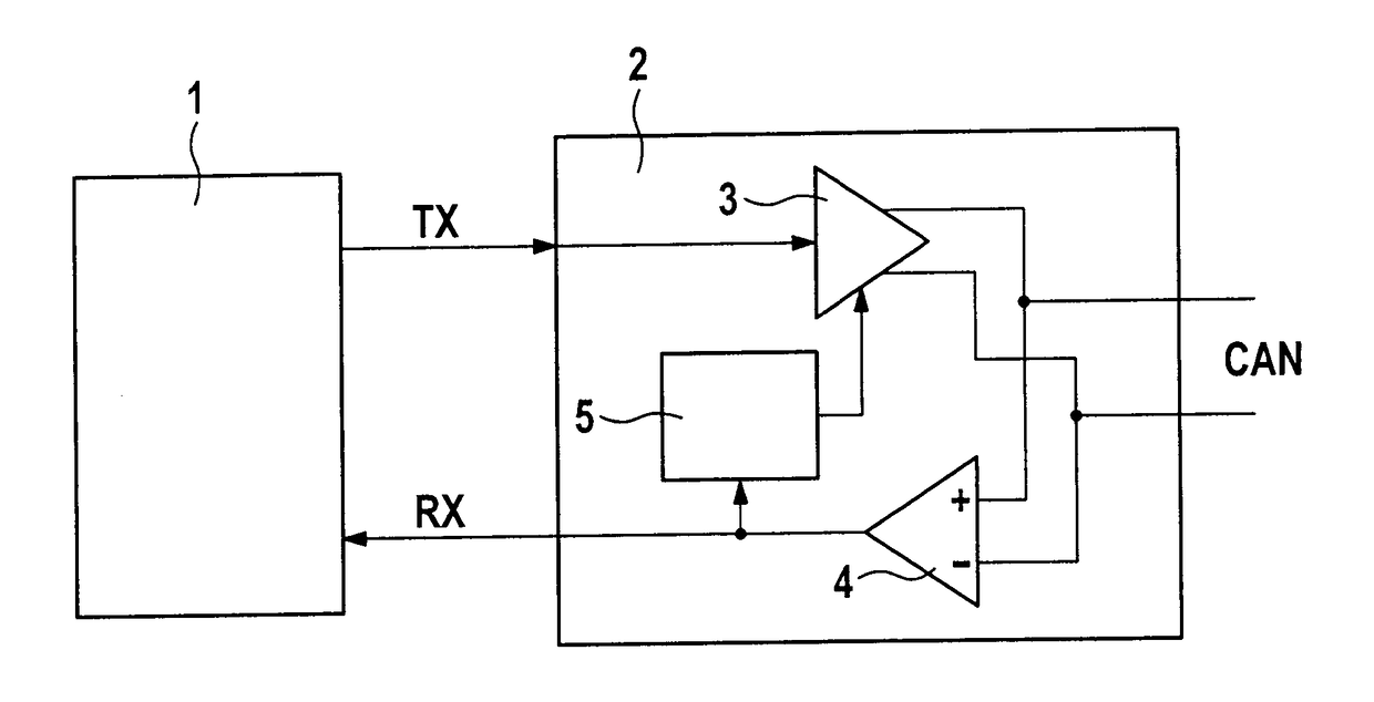
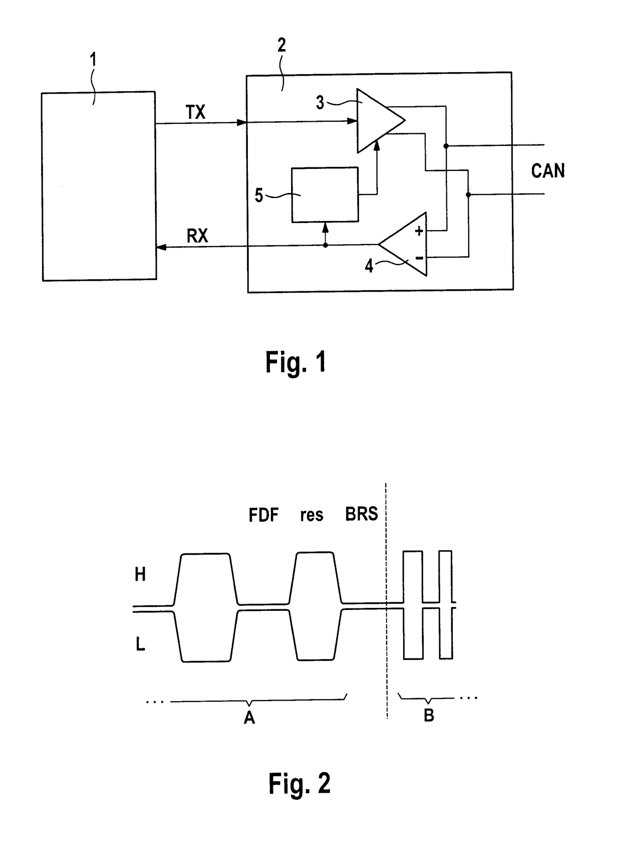
[0033]FIG. 1 shows an exemplary schematic illustration of a CAN controller 1 and a CAN transceiver 2 that communicate by means of transmission line TX and reception line RX. For the purpose of sending data via data bus CAN, transmission line TX is connected to output driver 3 of transceiver 2. For the purpose of receiving data, reception line RX is connected to receiver 4 of transceiver 2. While output driver 3 is sending data, said data can be read by receiver 4 at the same time in a manner that is known per se, this being used by the CAN controller particularly when sending the identifier in the arbitration phase. Transceiver 2 additionally has decoder 5, which can be used to decode read CAN data frames in a low energy mode of partial networking at least to some extent.

[0034]FIG. 2 shows an exemplary timing for a transition from an arbitration phase to a data phase for a CAN-FD data frame. According to an aspect of the invention, decoder 5 of transceiver 2 detects the BRS (“bit ra...


PUM


Abstract

A method for transmitting messages in a data bus system, wherein the messages can be transmitted in the form of data frames by a data bus and a data frame that is to be sent by a bus subscriber is checked for a piece of changeover information, which method is furthermore distinguished in that changeover of the rise time and / or edge shape of edges of bit pulses of the data frame that is to be sent is performed on the basis of the presence of a defined value of the piece of changeover information. In addition, a corresponding transceiver and to an electronic control unit is disclosed.

Description

CROSS REFERENCE TO RELATED APPLICATIONS[0001]This application is the U.S. National Phase Application of PCT International Application No. PCT / IB2015 / 000748 filed Mar. 26, 2015, the contents of such application being incorporated by reference herein.FIELD OF THE INVENTION[0002]The present invention relates to a method for transmitting messages in a data bus system to a transceiver for a bus subscriber of a data bus system and to a corresponding electronic control unit for a motor vehicle.BACKGROUND OF THE INVENTION[0003]Data bus systems are used in many diverse technical areas. Examples are automotive and aviation engineering, where particularly the communication of electronic control units (ECU) is realized using bus systems, such as CAN bus. If messages are sent from one bus subscriber to all further bus subscribers in a bus system, this is referred to as what is known as a broadcast method. If this involves the data bus operating without defined time windows in which a particular ...

Claims


Application Information

Patent Timeline
Patent Type & Authority Applications(United States)
IPC IPC(8): H04L12/40
CPCH04L12/4013H04L12/40169H04L2012/40215H04L2012/40273
Inventor BECKMANN, TOBIASJANISZEWSKI, IRENEUSZCORNELIUS, CLAASTURPIN, PIERREALEXANDROVICH KULKOV, EUGENYGACH, ROBERTSERGEEVICH RYABCHENKOV, SERGEY
Owner CONTINENTAL TEVES AG & CO OHG
Why Eureka
Eureka Blog
Learn More