

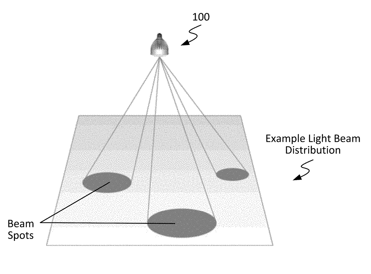
Solid state lighting device with electronically adjustable light beam distribution
a solid-state lighting and electronic control technology, applied in semiconductor devices for light sources, lighting and heating apparatuses, electroluminescent light sources, etc., can solve the problems of existing approaches to providing electronically controlled light distribution generally, high cost of such designs, and large form factors for retrofit applications, so as to reduce the quantity of components and the amount of electrical wiring, and facilitate the adjustment. , the effect of eliminating or otherwise reducing difficulties
- Summary
- Abstract
- Description
- Claims
- Application Information
AI Technical Summary
Benefits of technology
Problems solved by technology
Method used
Image

Examples
Embodiment Construction
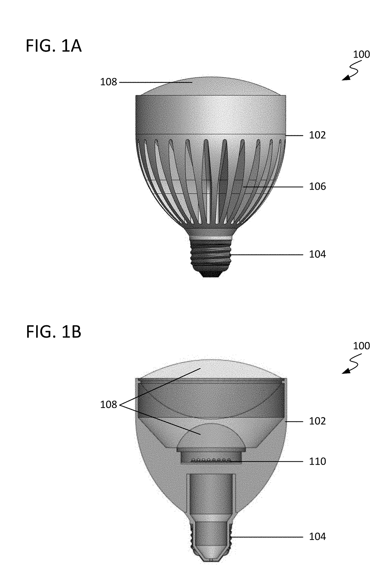
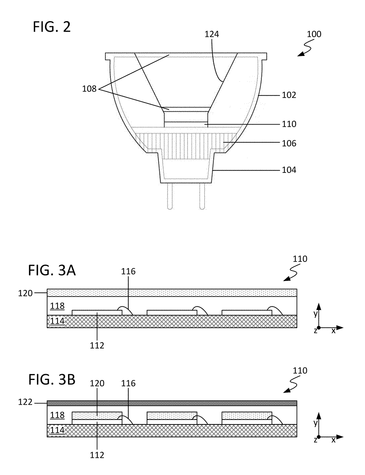
[0024]For ease of description, embodiments are described throughout with reference to a lamp (i.e., a lighting device having a socket similar to a socket found on a traditional light source), though embodiments are not so limited and include any known type of lighting device. FIGS. 1A-1B are side and cross-sectional views, respectively, of a lamp 100 including one or more solid state light sources configured in accordance with an embodiment of the present disclosure. FIG. 2 is a cross-sectional view of a lamp 100 configured in accordance with another embodiment of the present disclosure. As will be appreciated in light of this disclosure, a lamp 100 configured as variously described herein may be compatible with power sockets / enclosures typically used in existing luminaire structures, such as, for example: MR16 or other multi-faceted reflector (MR) configuration; PAR16, PAR20, PAR30, PAR38, or other parabolic aluminized reflector (PAR) configuration; BR30, BR40, or other bulged refl...
PUM
 Abstract
Description
Claims
Application Information