Device for detecting radiation and associated detection device

Active Publication Date: 2018-03-15
COMMISSARIAT A LENERGIE ATOMIQUE ET AUX ENERGIES ALTERNATIVES
View PDF0 Cites 8 Cited by
  • Summary
  • Abstract
  • Description
  • Claims
  • Application Information

AI Technical Summary

Benefits of technology

The invention is a device that uses optical sensors to measure radiation levels in a flexible cable. The device has several advantages over conventional detectors, including the absence of electronics in the cable and the ability to measure high dose rates. The device can be calibrated to account for temperature variations and has a long lifespan compared to conventional detectors. Additionally, the device uses small detectors and optical fibers with small diameters, which results in increased measurement capability for the same cable size. The device can be used for various clean-up applications and its flexible design allows for long cable lengths.

Problems solved by technology

Respecting the ALARA (“As Low As Reasonably Achievable”) principle has significant regulatory, economic and logistic repercussions on work organisation.
The presence of the sandwich half-tubes T1, T2 does not enable curves to be crossed.
This device can thus be only used in rectilinear ducts.
Moreover, thermo-luminescent dosimeters do not allow for an operational use since they require to dismantle the assembly after each exposure, and then, to transmit the dosimeters to a specialised laboratory to make measurements.
Indeed, Geiger-Muller detectors, even miniature ones, remain relatively bulky.
Thereby, it is not possible to perform dose rate measurements in ducts having a very low diameter such as, for example, conduits with an 8 mm diameter.
Another drawback of Geiger-Muller detectors is that they require a high voltage supply and that they are “illuminated” by high dose rates.
In addition, the transmission of a measurement signal is disturbed when the cable length is too large (for example, beyond 20 m) and the resolution of the miniature Geiger-Muller detector offset by a large cable length is in the order of one mGy / h, which is not sufficient at the ultimate decontamination stages where the dose rate reaches values of a few μGy / h.
A common drawback of both above-described devices of prior art is that they have to be installed by drawing, thereby requiring the presence of an access to each of both ends of the duct to be analysed.
Another common drawback of both devices is that the ducts in question have a relatively high diameter, typically between 25 mm and 50 mm.

Method used


Image

  • Device for detecting radiation and associated detection  device
  • Device for detecting radiation and associated detection  device
  • Device for detecting radiation and associated detection  device

Examples


Embodiment Construction

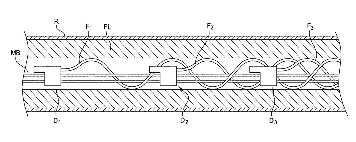
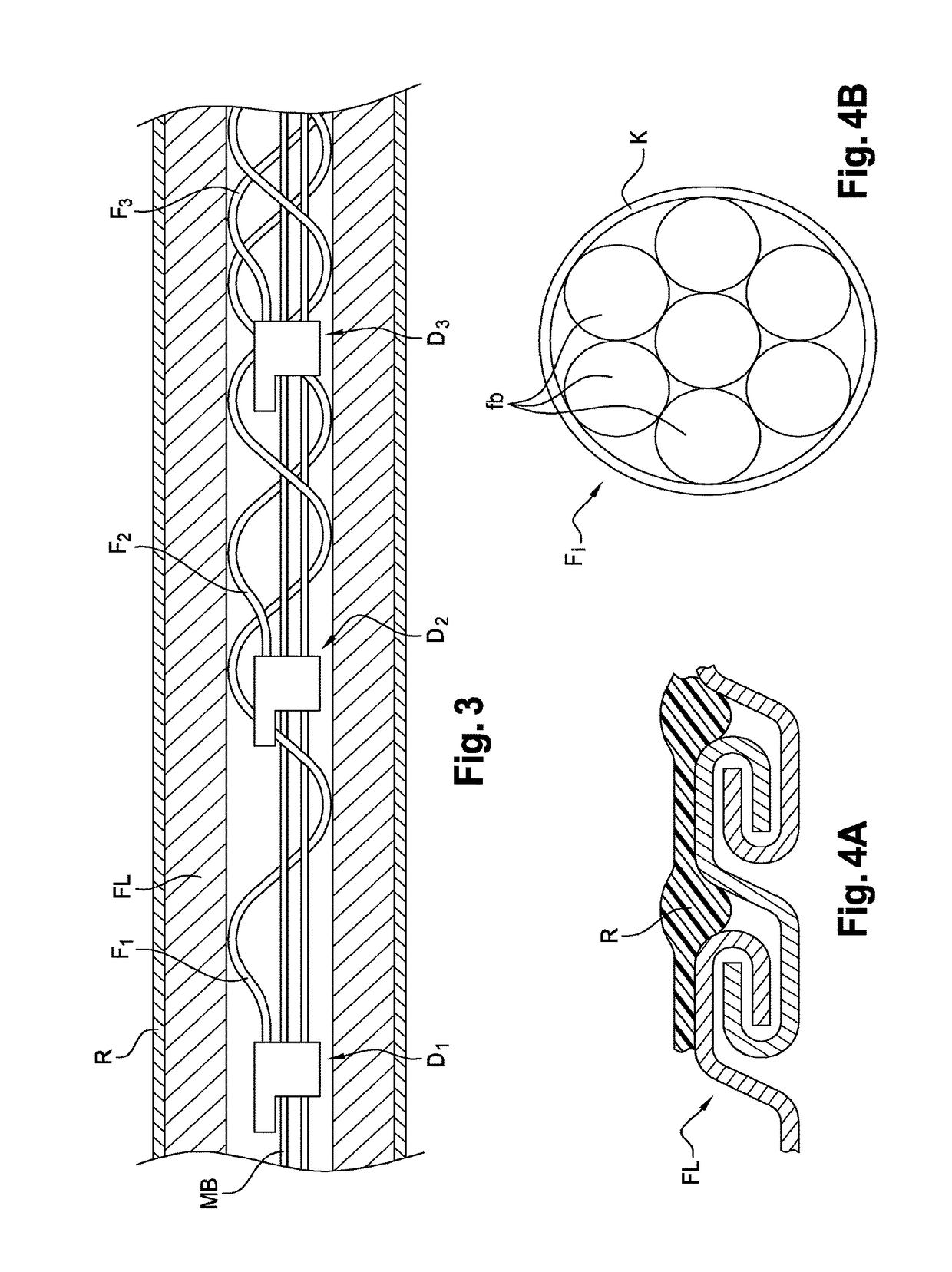
[0052]FIG. 3 represents a schematic diagram of essential elements which make up a radiation-detecting device according to the invention and FIGS. 4A-4D represent detail views of the detecting device of the invention.

[0053]The device comprises a set of OSL detectors Di (i=1, 2, 3, etc.) placed in the flexible cable FL. The detectors Di are connected to each other using a support cable MB. Each detector Di is equipped with a beam of fibres Fi. FIG. 4C represents a longitudinal cross-section view of a detector D. FIG. 4D represents a transverse cross-section view of the same detector.

[0054]The flexible cable FL is preferentially an interlocked metal hose. The interlocked metal hose can be of the single lock or double lock type. The single lock hose has a greater flexibility and a higher internal / external diameter ratio than the double lock hose, but its mechanical strength is lesser.

[0055]In practice, for dismantling applications, a double lock hose such as that represented, for exampl...


PUM


Abstract

A radiation-detecting device including at least two radiation detectors distributed in series along a support cable, each detector including an optically stimulated luminescence detection element which is optically coupled to at least one optical fiber, each optically stimulated luminescence detection element being held opposite a first end of the optical fiber by a mechanical part fixed to the support cable, the mechanical part being held in a flexible cable by a holding mechanism, second ends of each optical fiber leading to the same first end of the flexible cable.

Description

TECHNICAL FIELD AND PRIOR ART[0001]The invention relates to a radiation-detecting device as well as a detecting system able to determine radiations present in a facility.[0002]The radiations concerned are, for example, photons with an energy between 50 KeV and 6 MeV, or even more, electrons with an energy higher than one MeV, etc.[0003]The protection of people from radiation which intervene in an electronuclear environment is obligatory for the purpose of minimising the exposure thereof. Respecting the ALARA (“As Low As Reasonably Achievable”) principle has significant regulatory, economic and logistic repercussions on work organisation.[0004]A personnel dosimetry is thus implemented at all the steps of a fuel cycle, from its preparation to the monitoring of a plant operation, to the follow-up of its clean-up for the dismantling thereof and the storage of waste resulting from the deconstruction thereof. Dismantling techniques (i.e. robotics, remote control operation, dosimetry) have...

Claims


Application Information

Patent Timeline
IPC IPC(8): G01T1/20G01T1/203
CPCG01T1/2012G01T1/201G01T1/203G01T1/2002G01T1/10G01T7/00
Inventor MAGNE, SYLVAINBOUDERGUI, KARIMMAKIL, HAMID
Owner COMMISSARIAT A LENERGIE ATOMIQUE ET AUX ENERGIES ALTERNATIVES
Why Eureka
Try Eureka