Modular fiber frame
a module and fiber technology, applied in the field of modules, can solve the problems of increasing the density of connection, affecting the performance of the connection, and affecting the reliability of the connection, so as to achieve the effect of increasing the connection density
- Summary
- Abstract
- Description
- Claims
- Application Information
AI Technical Summary
Benefits of technology
Problems solved by technology
Method used
Image
Examples
first embodiment
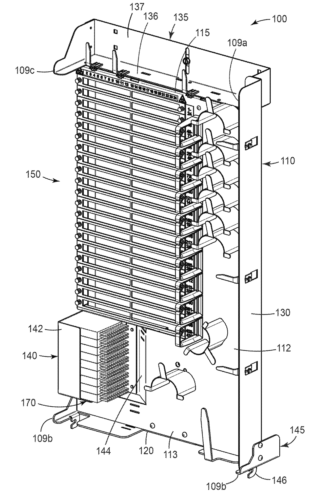
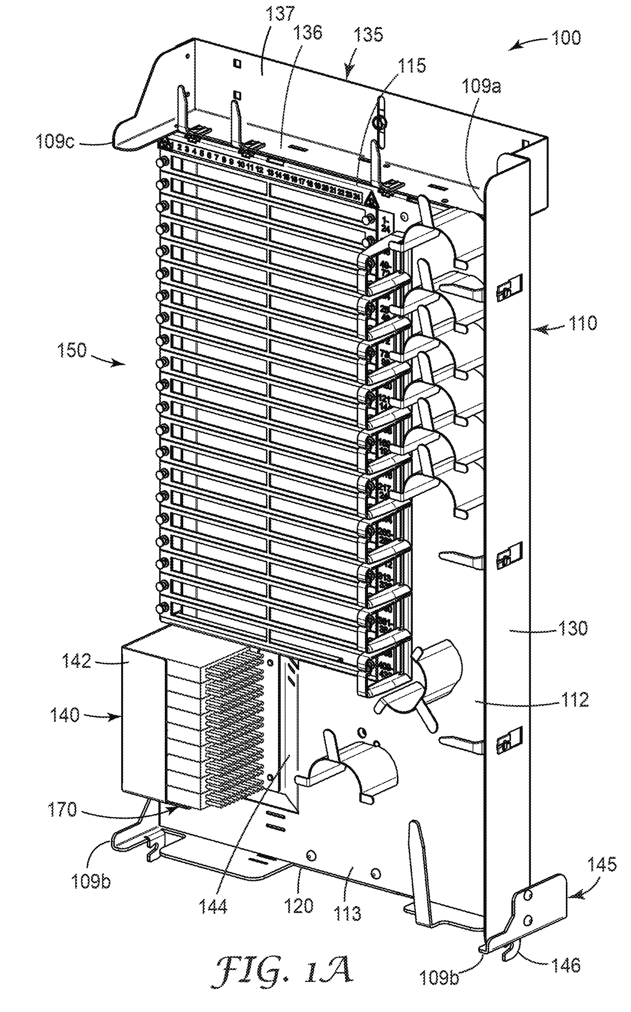
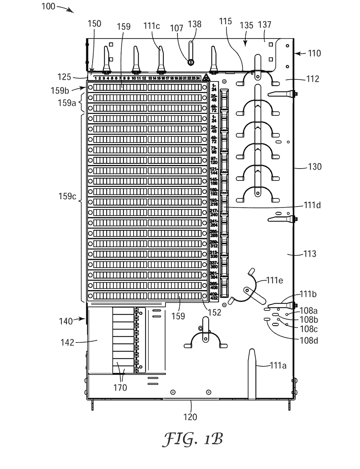
[0031]an exemplary modular fiber frame 100 is shown in FIGS. 1A-1E. Modular fiber frame 100 includes a frame body 110 and a connection module 150. The frame body comprises a flat face portion 112 has a generally rectangular shape having four edges: a top edge 115, a bottom edge 120, and two side edges 125, 130. The face portion has a front side (the first major surface) 113 and a back side 114 (the second major surface disposed opposite the first major or the front side). One or more of the edges can be bent so that it forms an L-shape with the face portion to provide structural support for the frame body as well as aiding in containing and protecting the optical fibers routed on the front side of the face portion. In the embodiment shown in FIG. 1A the second side edged 130 is bent so that it extends generally perpendicular to the face portion of the frame body.
[0032]Frame body 110 includes a splitter bracket 140 disposed adjacent to first edge 135 and below connection module 150. ...
second embodiment
[0071]FIG. 10 shows a modular fiber frame 200 having a distribution connection capacity of 288 with 24 feeder connections and 24 pass through connections and utilizes one 288 fiber cable harness and one 48 fiber cable harness split between the feeder and pass through connections. In this embodiment the optical splitter modules 270 have been moved to the right hand side of the frame body 210 and are oriented so that the splitter pigtails (not shown) exit the optical splitter module toward the bottom of the frame body.
[0072]The connection module in this embodiment includes 28 connection plates 252; each connection plate is configured to hold twelve SC optical fiber connector adapters 254. In an exemplary aspect, modular fiber frame 200 is configured to fit in a bay of a telecommunication cross-connect cabinet that is about 13 inches across the face of the bay, about 31 inches tall and less than 6 inches deep.
third embodiment
[0073]FIG. 11 shows a modular fiber frame 300 having a distribution connection capacity of 432 with 48 feeder connections and 48 pass through connections. The pass through connections 308 are located on the frame body rather than on the connection module. In this embodiment, the connection panel 350 includes 40 connection plates 352; each connection plate is configured to hold twelve SC optical fiber connector adapters (not shown). In an exemplary aspect, modular fiber frame 300 is configured to fit in a bay of a telecommunication cross-connect cabinet that is about 13 inches across the face of the bay, about 46 inches tall and less than 6 inches deep.
[0074]FIGS. 12A-12C are three views of a fourth exemplary modular fiber frame 400 illustrating the ability to configure the volume of the modular fiber frame to function in multiple applications. FIG. 12A shows the frame body 410 with a first connection module 450 mounted on the upper half of the frame body, an opening 419 for mounting...
PUM
 Abstract
Description
Claims
Application Information
 - R&D
- Intellectual Property
- Life Sciences
- Materials
- Tech Scout
- Unparalleled Data Quality
- Higher Quality Content
- 60% Fewer Hallucinations
Browse by: Latest US Patents, China's latest patents, Technical Efficacy Thesaurus, Application Domain, Technology Topic, Popular Technical Reports.
© 2025 PatSnap. All rights reserved.Legal|Privacy policy|Modern Slavery Act Transparency Statement|Sitemap|About US| Contact US: help@patsnap.com


