Multi-engine aircraft power plant with heat recuperation

a multi-engine aircraft and power plant technology, applied in the direction of jet propulsion plants, turbine/propulsion fuel control, mechanical equipment, etc., can solve the problems of low fuel efficiency of both engines of helicopters operating at a reduced power output setting, relatively long flight periods, and not operating within the optimal performance window of engines

Active Publication Date: 2018-03-22
PRATT & WHITNEY CANADA CORP
View PDF12 Cites 36 Cited by
  • Summary
  • Abstract
  • Description
  • Claims
  • Application Information

AI Technical Summary

Benefits of technology

[0015]The method may comprise operating the first turboshaft engine at a substantially constant output power level while the output power level of the second turboshaft engine is increased.
[0016]The method may further comprise, after increasing the output power level of the second turboshaft engine, modulating the output power level of the second turboshaft engine based on a difference between the sensed speed value representative of the actual output speed of the multi-engine power plant and the corresponding set point value.

Problems solved by technology

When both engines of a twin-engine helicopter are operating at reduced power output, they are typically not operating within an optimum performance window of the engines.
Consequently, depending on the type of mission, both engines of the helicopter operating at a reduced power output setting may operate at a relatively low fuel efficiency (i.e. relatively high fuel consumption) for relatively long portions of a flight.

Method used


Image

  • Multi-engine aircraft power plant with heat recuperation
  • Multi-engine aircraft power plant with heat recuperation
  • Multi-engine aircraft power plant with heat recuperation

Examples


Embodiment Construction

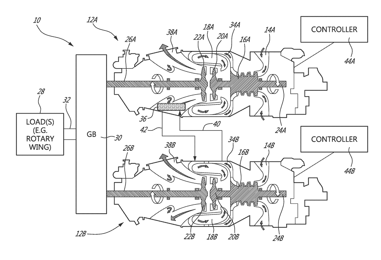
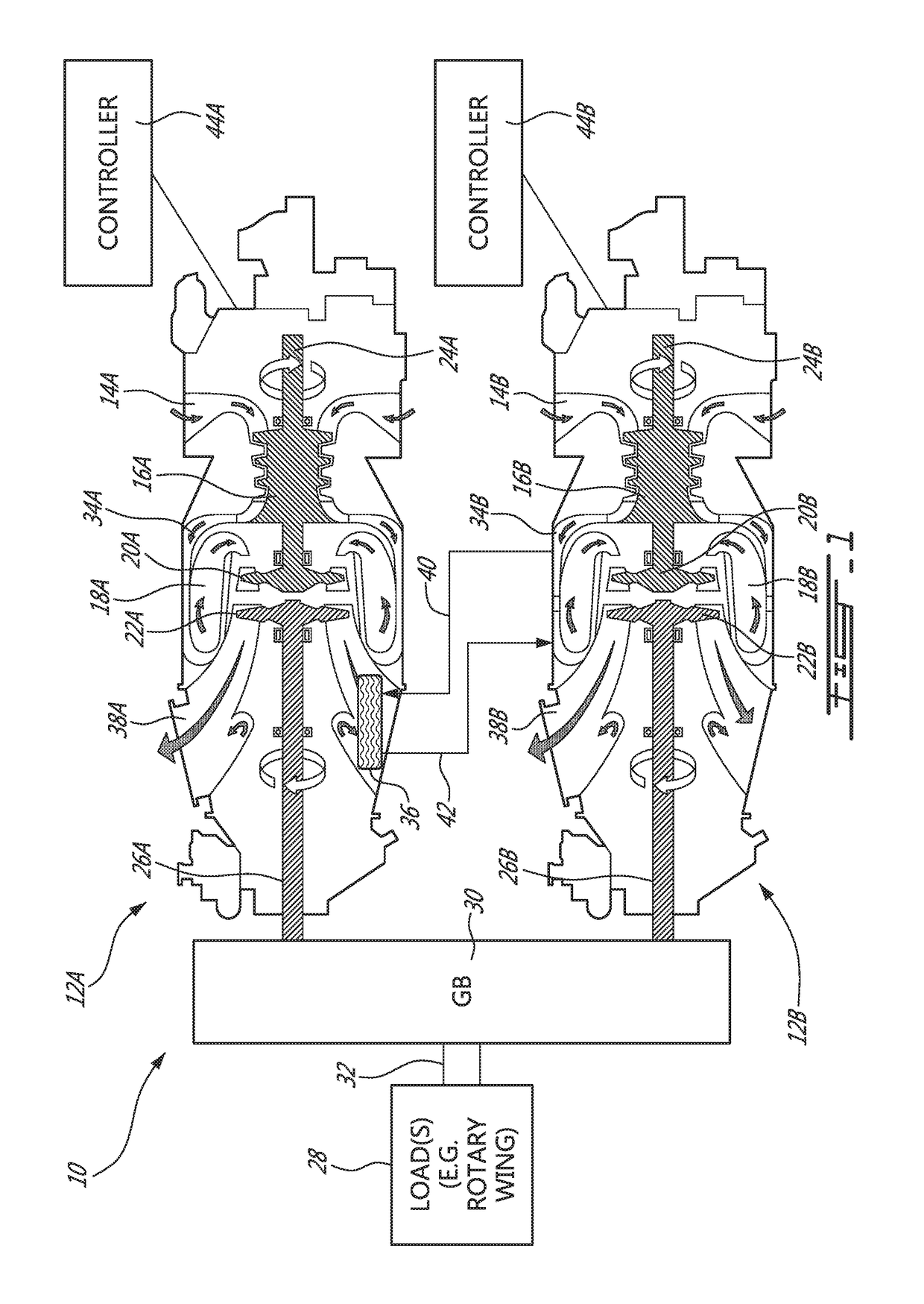
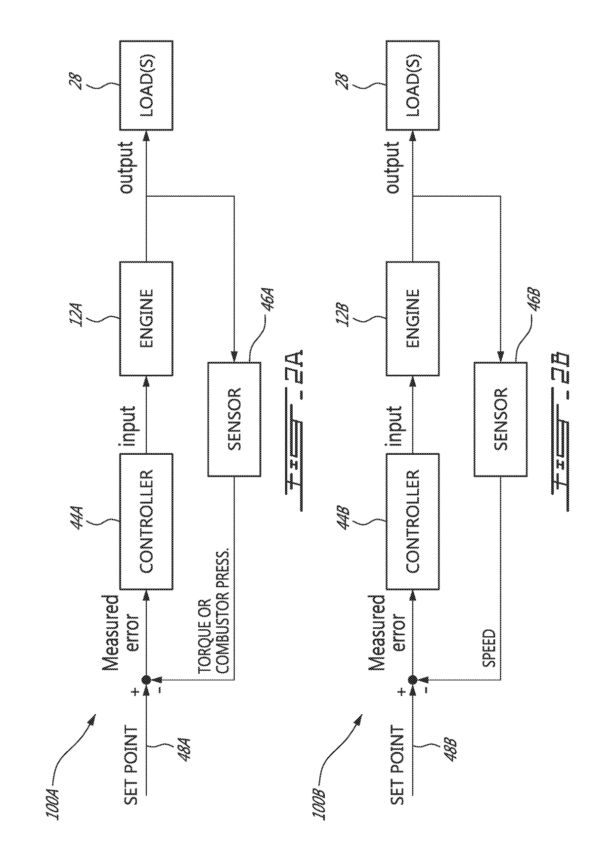
[0051]The present disclosure relates to configurations of multi-engine power plants for (e.g., rotary-wing) aircraft applications and associated methods of operation. In some embodiments, the disclosed configurations of multi-engine power plants may allow one engine of the power plant to idle when not needed and allow such engine to increase its out power level relatively rapidly when needed to supplement the driving engine or to take over for the driving engine in the event of a failure of the driving engine. In some embodiments, a cross-engine heat recuperation system may transfer waste heat from the driving engine to the idling engine in order to reduce the fuel consumption of the idling engine. In some embodiments, control (e.g., modulating) of the idling engine may be based on an operating speed of the load (e.g., main rotor of a helicopter) drivingly coupled to the multi-engine power plant so that a separate dedicated engine failure detection system may not be required to caus...


PUM


Abstract

Multi-engine aircraft power plants and associated operating methods are disclosed. An exemplary multi-engine power plant comprises a first turboshaft engine and a second turboshaft engine configured to drive a common load such as a rotary wing of an aircraft; and a heat exchanger in thermal communication with an exhaust gas of the first turboshaft engine and in thermal communication with pre-combustion air of the second turboshaft engine. The heat exchanger is configured to permit heat transfer from the exhaust gas of the first turboshaft engine to the pre-combustion air of the second turboshaft engine.

Description

TECHNICAL FIELD[0001]The disclosure relates generally to multi-engine power plants for aircraft applications, and more particularly to the operation multi-engine power plants for rotary-wing aircraft.BACKGROUND OF THE ART[0002]Twin-engine helicopters typically require both engines to operate at a relatively high power output during some phases of flight such as during take-off, for example. During other phases of flight such as cruise, power requirements may be significantly lower and therefore the power output from each engine may be significantly reduced. Even though only one of the two engines may be required during such other phases, it is typically required for safety reasons that both engines remain operating at all times during flight. In an emergency condition such as failure of one of the two engines, this allows the other engine to rapidly increase its power output to make up for the failed engine and take over. When the helicopter is at low altitude, it is imperative that...

Claims


Application Information

Patent Timeline
Patent Type & Authority Applications(United States)
IPC IPC(8): F02C6/02F02C3/04F02C6/18F02C6/20F02C7/10
CPCF02C6/02F02C3/04F02C6/18F05D2220/90F02C7/10F05D2220/60F02C6/20F02C9/42F05D2220/329
Inventor ALECU, DANIEL
Owner PRATT & WHITNEY CANADA CORP
Why Eureka
Try Eureka