
Optical system for head-mounted display system

a display system and optical system technology, applied in the field of optical systems for displays, can solve the problems of reducing the f/# of the lens of the hmd which uses a micro display, increasing the performance requirements of displays, and micro displays,

Active Publication Date: 2018-03-22
VALVE
View PDF2 Cites 10 Cited by
  • Summary
  • Abstract
  • Description
  • Claims
  • Application Information

AI Technical Summary

Benefits of technology

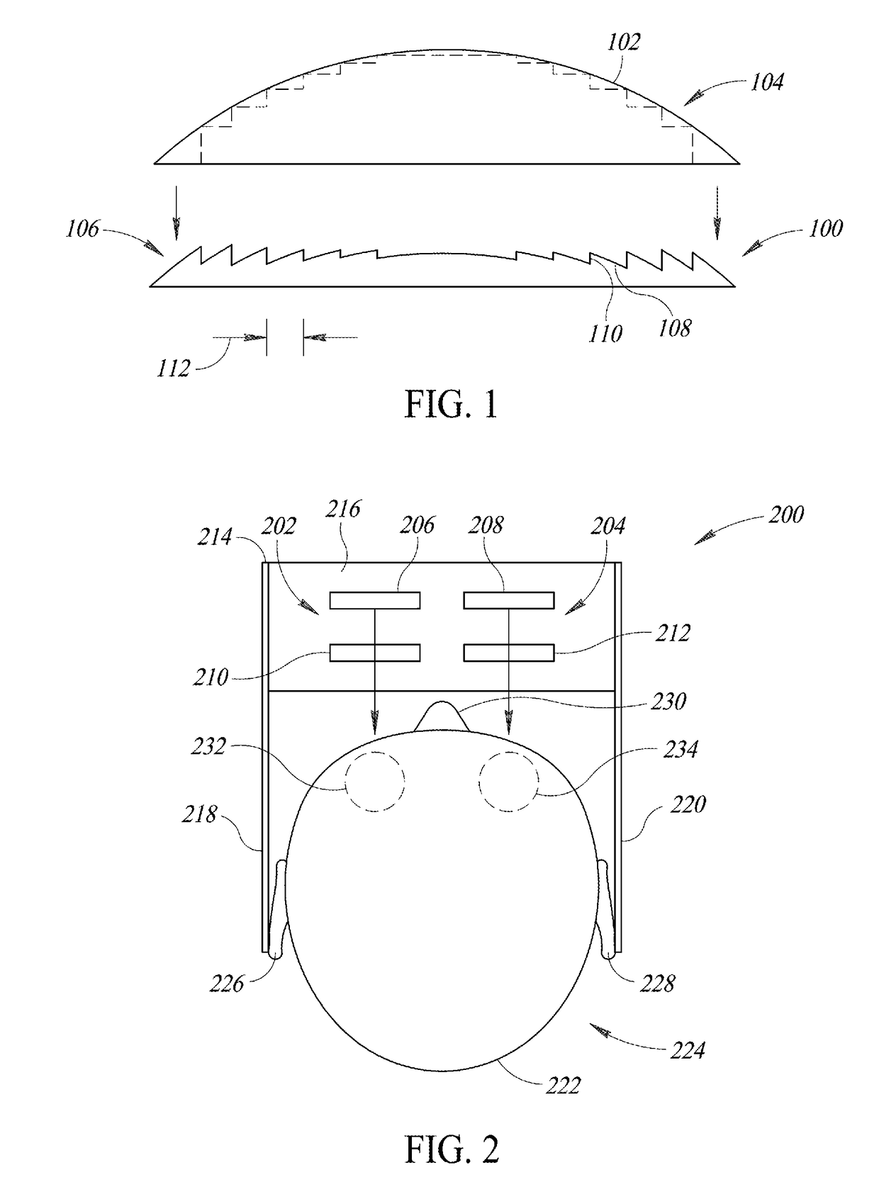
The patent describes a head mounted display system that includes two display subsystems for the user's eyes. Each subsystem includes a micro display and a lens element with Fresnel features. The lens element has different zones defined by different functions to provide a smooth transition for the user's eyes. The system has a combined focal length of less than 25 mm and a field of view of at least 85 degrees. The technical effect of the system is to provide a realistic and comfortable virtual or augmented reality display for the user.

Problems solved by technology

However, such head mounted displays, with reduced distance between a viewer's eye and the display and often with a fully obscured field of view, have increased the performance requirements of displays in ways that traditional displays cannot satisfy, let alone to do so at cost-effective levels.
Micro displays, such as OLED micro displays, are much smaller than traditional displays but involve additional challenges.
Further, because the eye pupil size of a user is fixed, the F / # of a lens of an HMD which uses a micro display is decreased, which tends to increase the aberrations of a particular lens system.
This increase the spatial resolution of the HMD optic further increases the challenge to design and manufacture the lens for such an HMD.

Method used


Image

  • Optical system for head-mounted display system
  • Optical system for head-mounted display system
  • Optical system for head-mounted display system

Examples


Embodiment Construction

[0019]In the following description, certain specific details are set forth in order to provide a thorough understanding of various disclosed implementations. However, one skilled in the relevant art will recognize that implementations may be practiced without one or more of these specific details, or with other methods, components, materials, etc. In other instances, well-known structures associated with computer systems, server computers, and / or communications networks have not been shown or described in detail to avoid unnecessarily obscuring descriptions of the implementations.

[0020]Unless the context requires otherwise, throughout the specification and claims that follow, the word “comprising” is synonymous with “including,” and is inclusive or open-ended (i.e., does not exclude additional, unrecited elements or method acts).

[0021]Reference throughout this specification to “one implementation” or “an implementation” means that a particular feature, structure or characteristic de...


PUM


Abstract

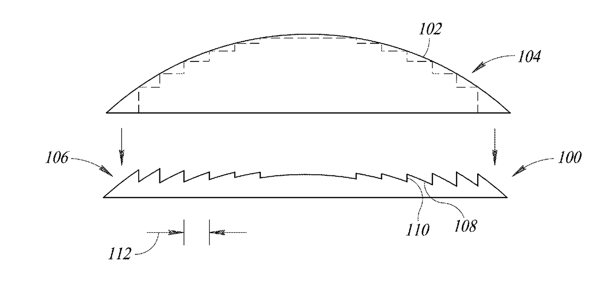
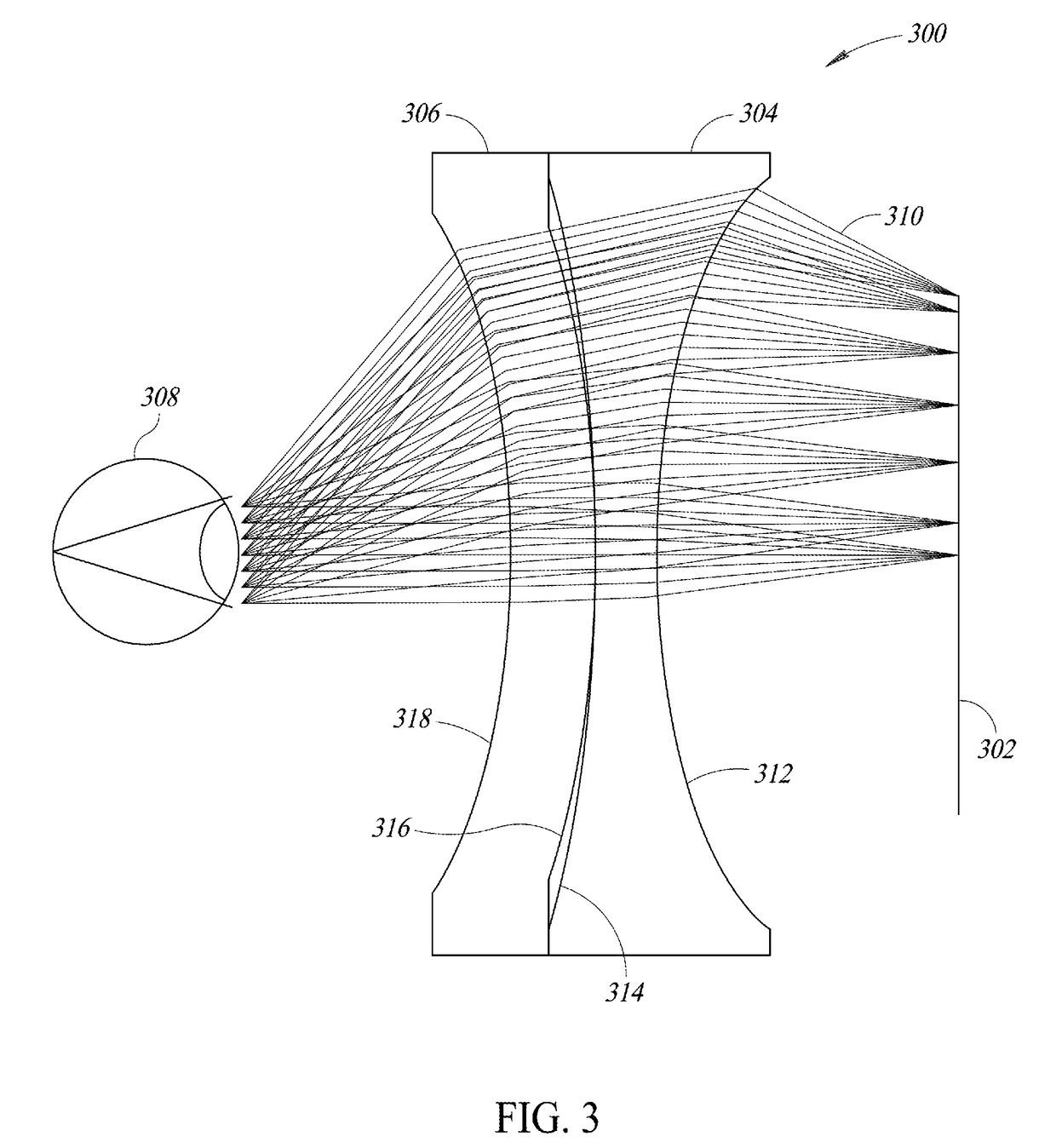
Systems and methods for providing optical systems which utilize double Fresnel lenses on curved surfaces for use with display systems, such as silicon-based micro display systems (e.g., OLED micro displays) used with head mounted display (HMD) systems. The optical systems disclosed herein may implement multiplexing or blending to provide a smooth profile transition and reduce aberrations between zones or fields (e.g., small FOV angles, large FOV angles) of a Fresnel surface which is defined by multiple Fresnel patterns or functions. An optical system for a micro display is provided which utilizes double Fresnel lenses on curved surfaces to shorten the focal length while maintaining a good shape factor for moldability and aberration control.

Description

BACKGROUNDTechnical Field[0001]The present disclosure generally relates to optical systems for displays, such as micro displays of head-mounted display systems.Description of the Related Art[0002]One current generation of virtual reality (“VR”) experiences is created using head-mounted displays (“HMDs”), which can be tethered to a stationary computer (such as a personal computer (“PC”), laptop, or game console), combined and / or integrated with a smart phone and / or its associated display, or self-contained. Generally, HMDs are display devices, worn on the head of a user, which have a small display device in front of one (monocular HMD) or each eye (binocular HMD). The display units are typically miniaturized and may include CRT, LCD, Liquid crystal on silicon (LCos), or OLED technologies, for example. A binocular HMD has the potential to display a different image to each eye. This capability is used to display stereoscopic images.[0003]Demand for displays with heightened performance ...

Claims


Application Information

Patent Timeline
IPC IPC(8): G02B3/08G02B3/04
CPCG02B3/08G02B3/04G02B2027/0132G02B27/0172G02B25/001G02B5/1895G02B2027/011G02B2027/0123G02B27/4216
Inventor HUDMAN, JOSHUA MARK
Owner VALVE
Learn More