This helps you quickly interpret patents by identifying the three key elements:
Problems solved by technology
Method used
Benefits of technology
Benefits of technology
The energy generation system controller described in this patent can optimize energy generation using a forward osmosis membrane, ensuring that energy usage does not exceed energy production. It can also prevent inappropriate operations and reduce the occurrence of events that cause inefficient energy generation, such as out-of-control operation and membrane stop.
Problems solved by technology
Even in the case where the amount of energy generated by the mixed water is large, when the energy used is too large, the energy generation system that uses the forward osmosis membrane 100 becomes useless.
Method used
Image
Click on the blue label to locate the original text in one second.
Reading with bidirectional positioning of images and text.
Examples
embodiment 1
[0090](General Outline)
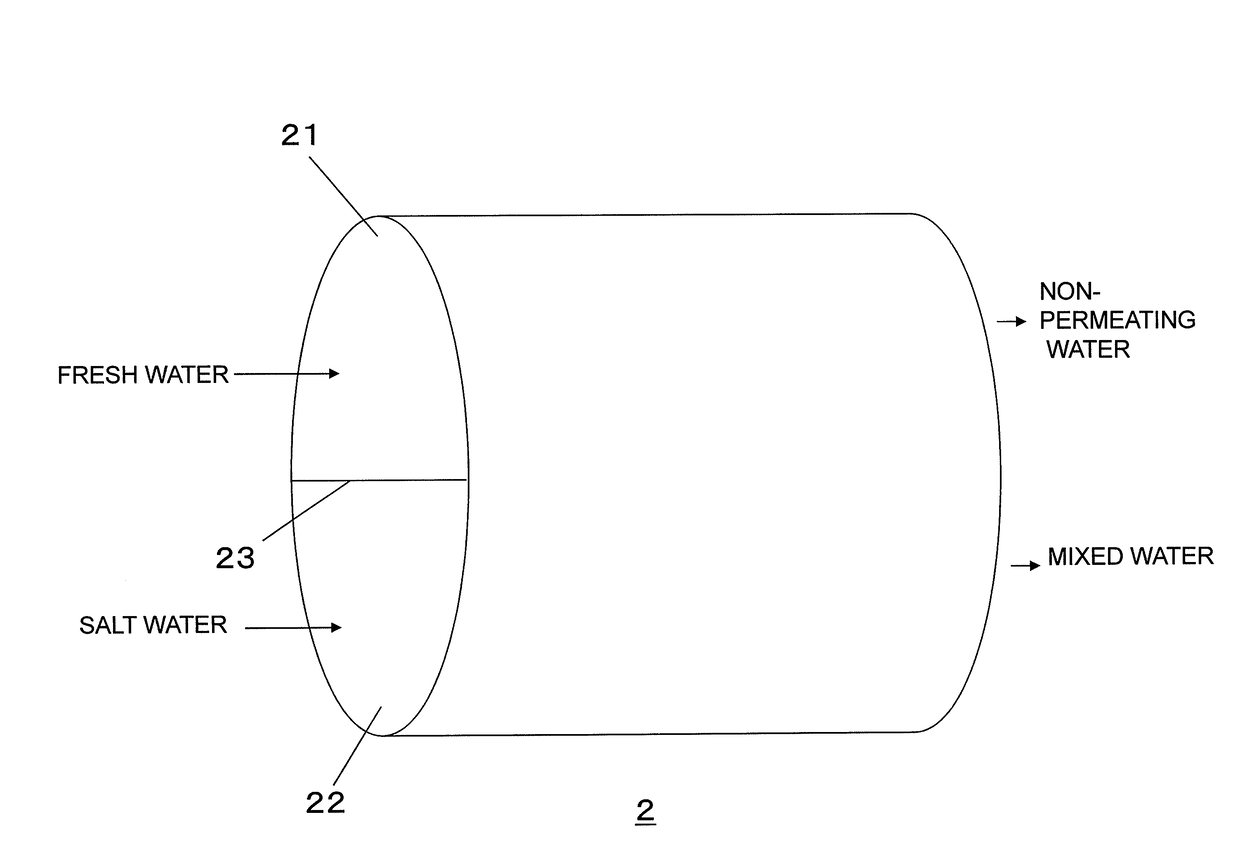
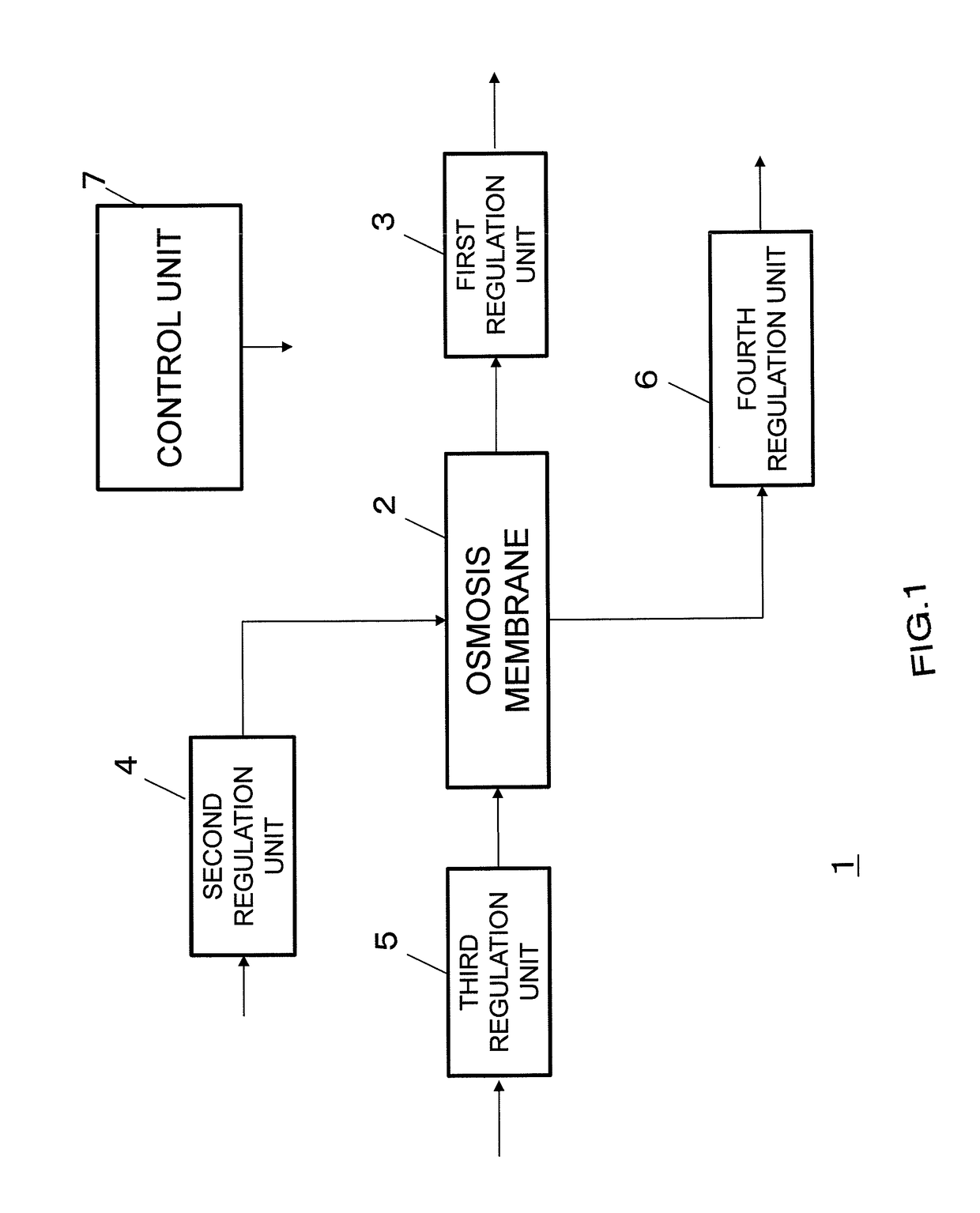
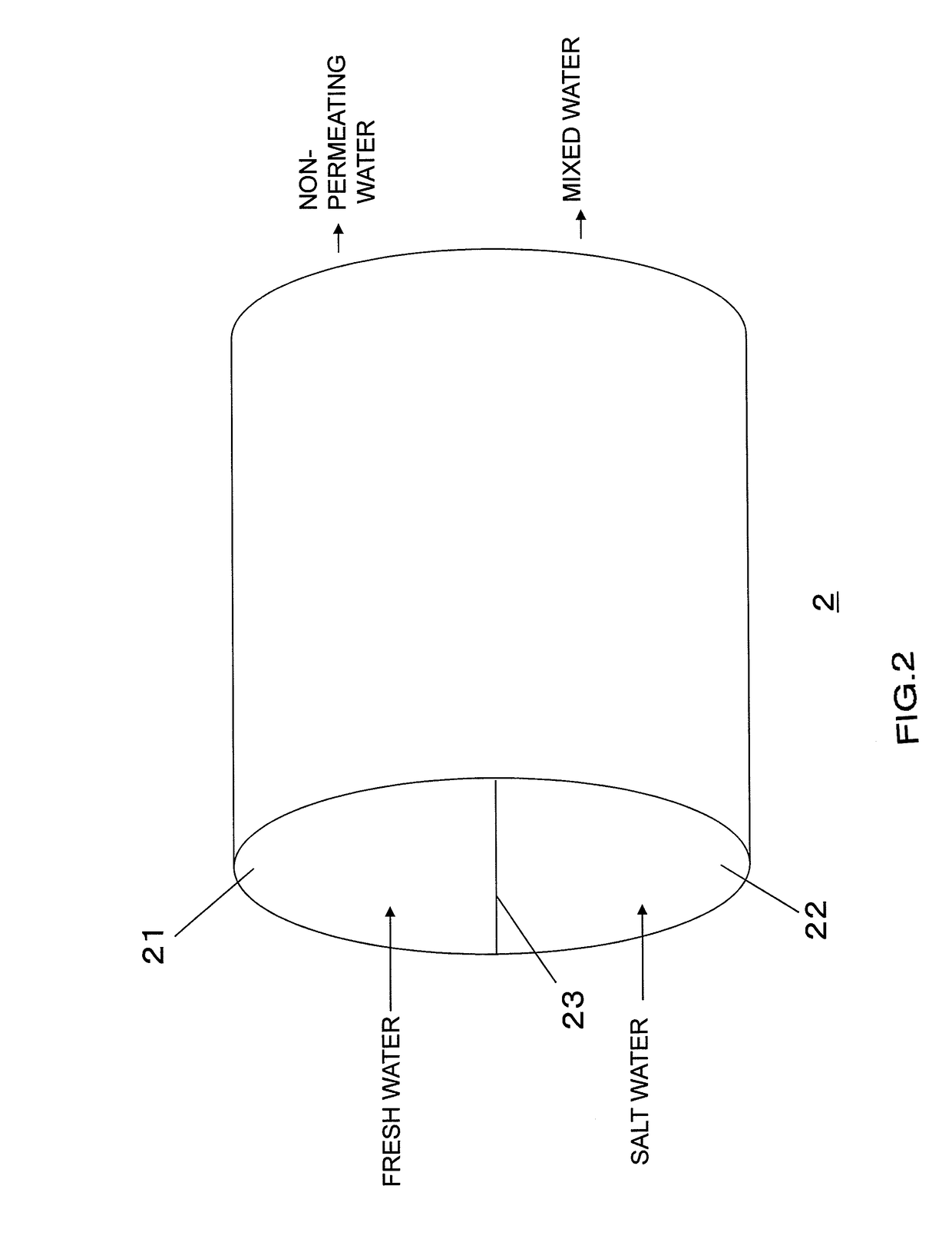
[0091]First, the general outline of a controller for an energy generation system in Embodiment 1 of the present invention will be described. FIG. 1 is a block diagram illustrating the controller for the energy generation system in Embodiment 1 of the present invention. A controller 1 for an energy generation system (hereinafter, referred to as “controller”) in FIG. 1 is used for an energy generation system that generates energy by using mixed water produced in a forward osmosis membrane 2. The energy generation system extracts energy by making use of the increased pressure of the mixed water produced in the forward osmosis membrane 2. This extracted energy is made use of by an electric generator, or is made use of in machine operation. In other words, the controller 1 is used in the energy generation system that uses the forward osmosis membrane 2.
[0092]The controller 1 includes a first regulation unit 3, a second regulation unit 4, a third regulation unit 5, ...
embodiment 2
[0143]Next, Embodiment 2 will be described. In Embodiment 2, the relationship between each of the regulation units and a corresponding one of the control signals.
[0145]The first regulation unit 3 regulates the discharge of non-permeating water from the forward osmosis membrane 2. As described in Embodiment 1, the control in the first regulation unit 3 is given a higher priority.
[0146]The first control signal controls this first regulation unit 3. The first control signal outputted from the control unit 7 controls an operation in the first regulation unit 3. The first regulation unit 3 includes, for example, a control valve 31 as illustrated in FIG. 6.
[0147]FIG. 6 is a block diagram illustrating the first regulation unit in Embodiment 2 of the present invention.
[0148]Based on the first control signal, the control valve 31 can change the degree of its own openness (sometimes closes itself), thereby regulating the discharge of non-p...
embodiment 3
[0171]Next, Embodiment 3 will be described. In Embodiment 3, an energy generation system that includes the controller 1 described in Embodiments 1 and 2 will be described.
[0172]FIG. 10 is a block diagram illustrating the energy generation system in Embodiment 3 of the present invention. FIG. 10 includes the controller 1 described in Embodiments 1 and 2. An energy generation system 50 includes the controller 1 described in Embodiments 1 and 2, a non-permeating-water discharge unit 32, a fresh water supply unit 42, a salt water supply unit 52, a mixed water discharge unit 62, and an energy generation unit 20.
[0173]The non-permeating-water discharge unit 32 discharges non-permeating water regulated by the first regulation unit 3. This discharge allows non-permeating water not having permeated in the forward osmosis membrane 2 to be discharged to the outside.
[0174]The fresh water supply unit 42 supplies fresh water regulated by the second regulation unit 4 to the forward osmosis membran...
PUM
Abstract
Provided is a controller for an energy generation system, the controller exerting optimum control so that, while a waste of energy is eliminated, any operation trouble is not caused. The controller for the energy generation system of the present invention is a controller for an energy generation system that uses a forward osmosis membrane, the controller including: a first regulation unit for regulating the discharge of non-permeating water from the forward osmosis membrane; a second regulation unit for regulating the supply of fresh water to the forward osmosis membrane; a third regulation unit for regulating the supply of salt water to the forward osmosis membrane; a fourth regulation unit for regulating the discharge of mixed water from the forward osmosis membrane; and a control unit for controlling the first regulation unit, the second regulation unit, the third regulation unit, and the fourth regulation unit.
Description
TECHNICAL FIELD[0001]The present invention relates to a controller for an energy generation system that generates energy by making use of a forward osmosis membrane.BACKGROUND ART[0002]In recent years, an energy generation system that generates energy by making use of a forward osmosis membrane has come to be used. The forward osmosis membrane has a configuration illustrated in FIG. 11 and FIG. 12, in which, when salt water is supplied to a salt water passage of the forward osmosis membrane and fresh water is supplied to a fresh water passage of the forward osmosis membrane, fresh water permeates the salt water passage from the fresh water passage. FIG. 11 is a schematic diagram illustrating the configuration of the forward osmosis membrane, and FIG. 12 is a schematic diagram for describing an osmosis phenomenon in the forward osmosis membrane.[0003]As illustrated in FIG. 11, a forward osmosis membrane 100 includes: a salt water passage 102 to which salt water is supplied and throug...
Claims
Application Information
Patent Timeline
Application Date:The date an application was filed.
Publication Date:The date a patent or application was officially published.
First Publication Date:The earliest publication date of a patent with the same application number.
Issue Date:Publication date of the patent grant document.
PCT Entry Date:The Entry date of PCT National Phase.
Estimated Expiry Date:The statutory expiry date of a patent right according to the Patent Law, and it is the longest term of protection that the patent right can achieve without the termination of the patent right due to other reasons(Term extension factor has been taken into account ).
Invalid Date:Actual expiry date is based on effective date or publication date of legal transaction data of invalid patent.

