Stator for an electric machine and method for production of such a stator

a technology of electric machines and stators, which is applied in the manufacture of stators/rotors, dynamo-electric machines, electrical apparatus, etc., can solve the problems of large limited space for machines to be built, failure/breakdown, and contradict the requirements of as little as possible insulating materials within electric machines, and achieve the effect of reliably preventing partial discharge and high fill factor

Inactive Publication Date: 2021-09-16
VOLKSWAGEN AG
View PDF4 Cites 0 Cited by
  • Summary
  • Abstract
  • Description
  • Claims
  • Application Information

AI Technical Summary

Benefits of technology

[0006]The present invention relates, therefore, to a stator in accordance with the definition of the species set forth in claim 1, respectively to a method in accordance with the definition of the species set forth in claim 8. It is an object of the present invention to provide a stator, respectively a method for manufacturing such a stator, which, on the one hand, will make it possible to achieve a high fill factor and, on the other hand, reliably prevent partial discharges.

Problems solved by technology

However, this contradicts the requirements for as little as possible insulating material within electric machines.
Though only the iron and copper components are electrically active, on the one hand, the available space for the machine to be built is greatly limited in many cases, on the other hand.
These partial discharges can damage or destroy the insulation system of the machine over the service life thereof, whereby a failure / breakdown could occur.
The disadvantage here is a reduced copper fill factor of the stator slots.
However, this entails a more complex manufacturing process.
This is not always possible since the boundary conditions are set in terms of input voltage and output voltage.

Method used


Image

  • Stator for an electric machine and method for production of such a stator
  • Stator for an electric machine and method for production of such a stator
  • Stator for an electric machine and method for production of such a stator

Examples


Embodiment Construction

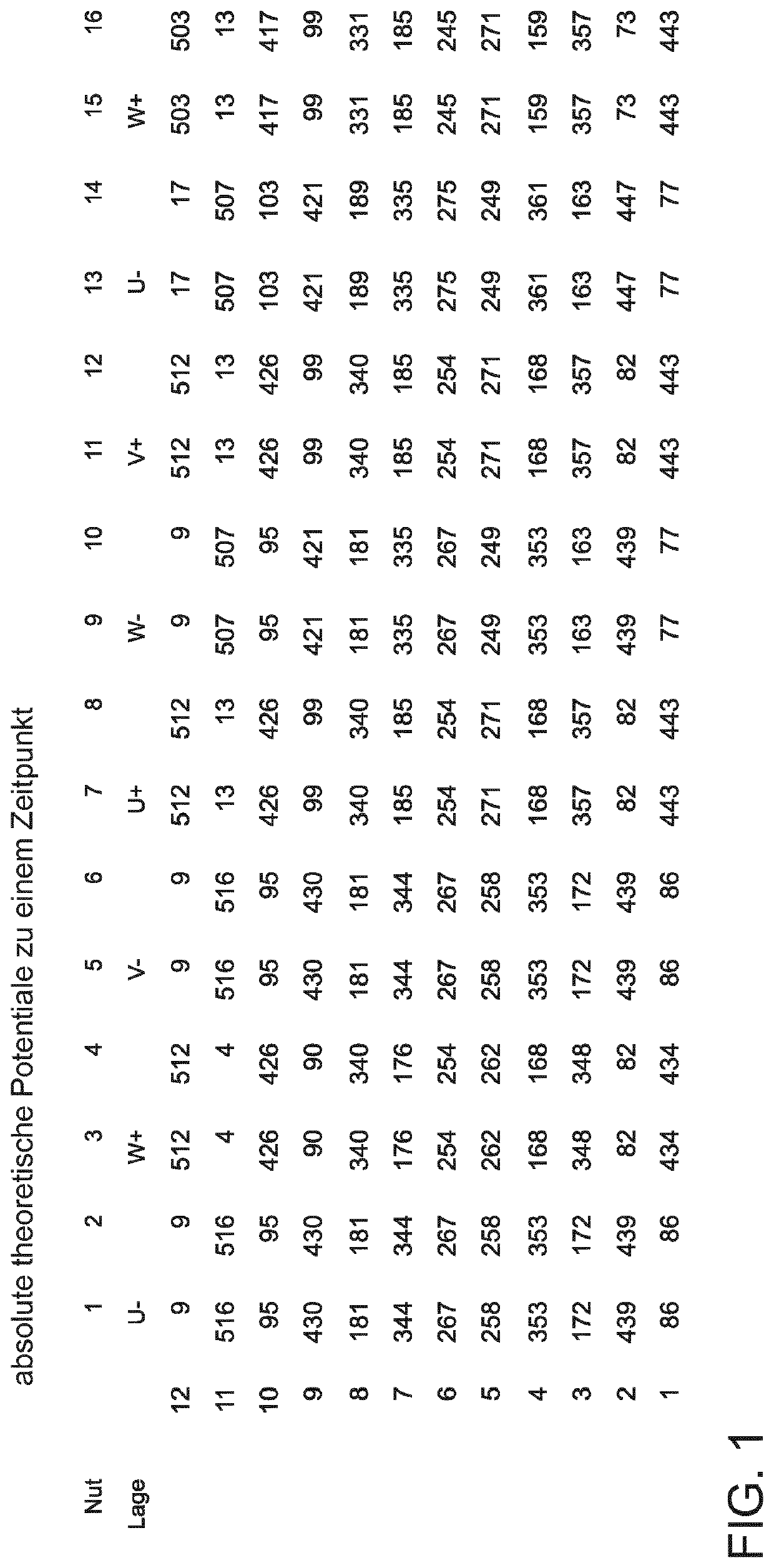
[0027]FIG. 1 shows a section of a table in which are entered the computationally determined absolute values of the potentials on the conductors in the individual slots at a specific point in time. The computation method is not described in greater detail here. In the present Application, in each particular case, the designation “conductors” means the sections of a winding that extend within a slot, along the same. In place of “conductors,”“conductor elements” could also be used.

[0028]FIG. 1 relates to a stator of a three-phase machine, for which a large amount (for example, 120) slots are provided, into which are inserted the conductors to which phases U, V, W of a three-phase current are applied. The present invention is applicable to all types of windings since the applied voltage drops across the entire line, so that different potentials prevail on the individual conductor elements.

[0029]The computations apply to all slots of the stator. In the present example, the stator has 120...


PUM


Abstract

A stator for an electric machine having slots for receiving conductors used for generating a magnetic field; in the slots, at least two mutually parallel, adjoining conductors being provided, which are electrically insulated from one another by insulation means; the insulations means being formed at least partially by a partition inserted between the conductors. It is an object of the present invention to provide a stator, respectively a method for manufacturing such a stator, which, on the one hand, will make it possible to achieve a high fill factor and, on the other hand, to reliably prevent partial discharges. The objective is achieved by the use and/or characteristics of the partitions being a function of the particular maximum voltage potential between the mutually parallel, adjoining conductors in the slots.

Description

BACKGROUND INFORMATION[0001]In device circuits of present-day machines, for example, during operation of electric motors driven by clocked inverter sources, there is an increase in recurring high-energy pulses (e.g., switching pulses). They have short rise times and peak voltages well above the nominal value of the supply voltage. These pulses allow insulation systems to age differently than under conventional AC voltage at system frequency. The following points must be thereby taken into consideration: Partial discharges destroy the insulation because of aggressive decomposition products, UV radiation and ozone, and because of electromechanical fatigue caused by the current pulses and because of dielectric heating due to the high-frequency components of the voltage pulses. Superimposed pulses can ignite partial discharges even if the nominal voltage is below the partial-discharge inception voltage. The temperature, air humidity, pulse shape, pulse polarity, and pulse repetition rat...

Claims


Application Information

Patent Timeline
Patent Type & Authority Applications(United States)
IPC IPC(8): H02K3/34H02K3/28H02K3/40H02K15/00H02K15/02
CPCH02K3/34H02K3/28H02K15/024H02K15/0068H02K3/40H02K3/32
Inventor EINFELD, HAUKEWINTER, JANHELMER, RAINERBRÜGGEMANN, MARCO
Owner VOLKSWAGEN AG
Why Eureka
Try Eureka