Sump tank for a gas turbine engine

a gas turbine engine and sump tank technology, which is applied in the direction of engine fuction, machines/engines, lubrication elements, etc., can solve the problems of sump tank sway, lubricant to slosh within the tank, and the sump tank is in a state of static tilt condition,

Active Publication Date: 2018-03-29
SOLAR TURBINES
View PDF0 Cites 2 Cited by
  • Summary
  • Abstract
  • Description
  • Claims
  • Application Information

AI Technical Summary

Problems solved by technology

Depending on how the vessel is loaded, the vessel may be tilted resulting in a static tilt condition of the sump tank.
When the vessel is operating in open water the swells may result in a dynamic tilt that causes t...

Method used


Image

  • Sump tank for a gas turbine engine
  • Sump tank for a gas turbine engine
  • Sump tank for a gas turbine engine

Examples


Embodiment Construction

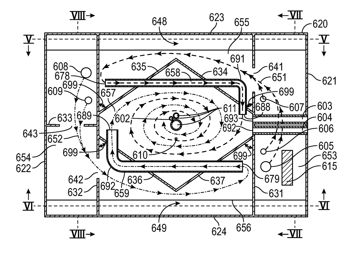
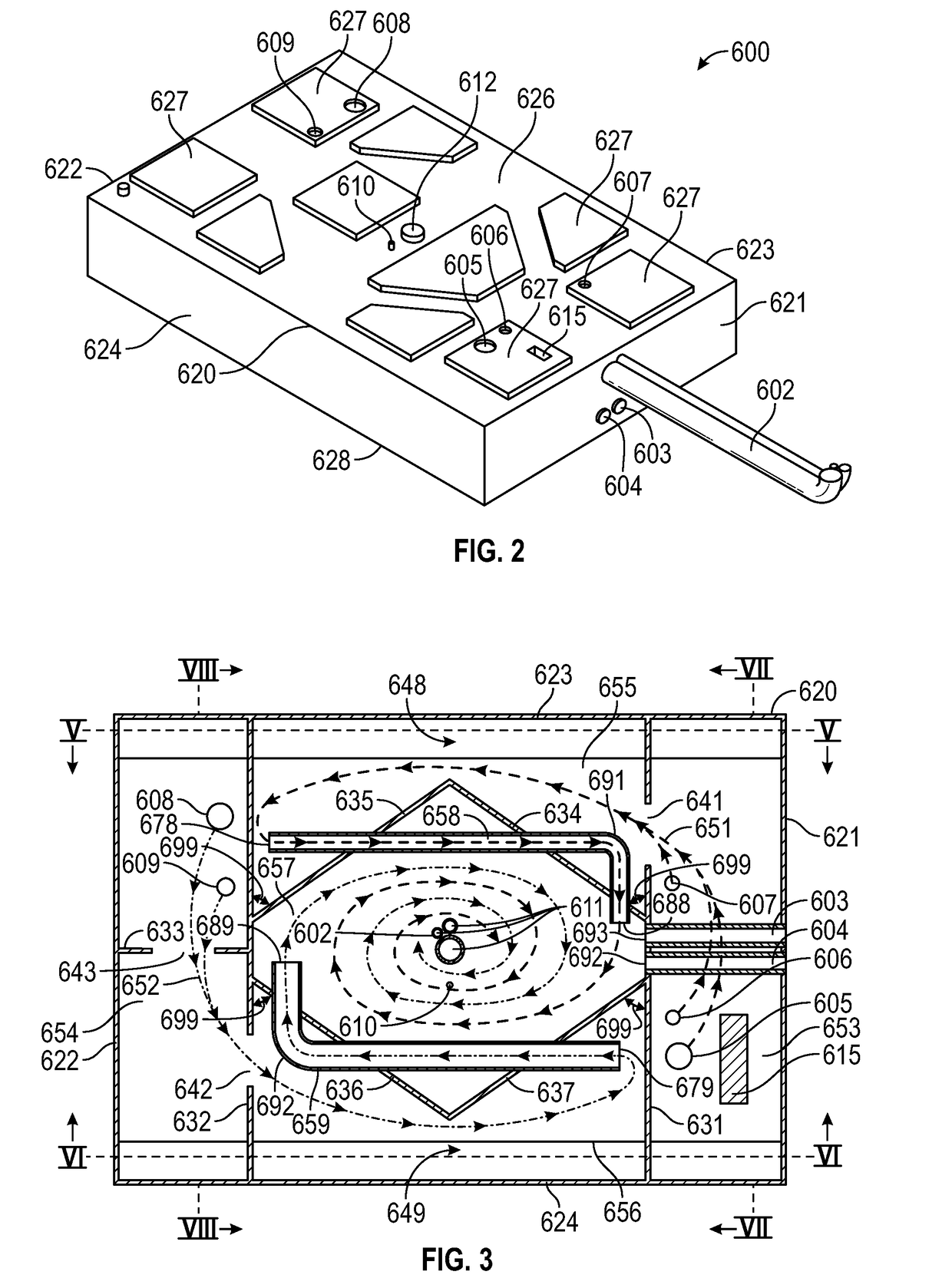
[0017]The systems and methods disclosed herein include a sump tank for a gas turbine engine capable of handling offshore motion. In embodiments, the sump tank includes two end compartments, two side compartments, a central compartment, and two tubes. The sump tank includes two lubricant flow paths, each including an end compartment, a side compartment, a tube, and the central compartment that form a circuitous path for the lubricant to follow from the return location(s) to the suction line(s). The baffles used to form the central compartment are angled so as to cause the lubricant entering from the tubes to swirl, which may increase the residence time of the lubricant and may help ensure that any entrained air is released from the lubricant prior to entering the suction line(s).

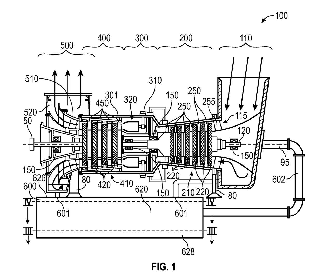
[0018]FIG. 1 is a schematic illustration of an exemplary gas turbine engine package including a gas turbine engine 100 and a sump tank 600. Some of the surfaces have been left out or exaggerated (here and in ...


PUM


Abstract

A sump tank for use with a gas turbine engine in offshore conditions is disclosed. In embodiments, the sump tank includes two circuitous lubricant flow paths. Each flow path includes an end compartment, a side compartment, and a tube that feed to a central compartment. The baffles used to form the central compartment are angled so as to cause the lubricant entering from the tubes to swirl, which may increase the residence time of the lubricant and may help ensure that any entrained air is released from the lubricant prior to entering the suction line.

Description

TECHNICAL FIELD[0001]The present disclosure generally pertains to a sump tank for a gas turbine engine, and is directed toward a sump tank capable of handling offshore motion.BACKGROUND[0002]Various sub systems of gas turbine engines and the equipment driven by the gas turbine engine require lubrication. The sump tank acts as a reservoir for the lubricant. A sump tank used on an offshore vessel is subjected to static and dynamic offshore conditions. Depending on how the vessel is loaded, the vessel may be tilted resulting in a static tilt condition of the sump tank. When the vessel is operating in open water the swells may result in a dynamic tilt that causes the sump tank to sway. Swaying the sump tank may cause the lubricant to slosh within the tank. Static and dynamic tilt conditions can cause lubricant levels to vary within the sump tank. Uneven lubricant levels may apply back pressure to lubricant return lines and may expose lubricant suction lines to air pockets.[0003]The pres...

Claims


Application Information

Patent Timeline
IPC IPC(8): F01D25/18
CPCF01D25/18F05D2260/98F05D2220/32F01M11/0004F01M11/08F16N39/002F16N31/004F01M11/064F01M11/065
Inventor MULOCK, MARK JUSTIN
Owner SOLAR TURBINES
Why Eureka
Try Eureka