Method for Optimizing Control Parameters of Cooling Fan and System Thereof

a technology of control parameters and cooling fans, applied in the direction of process and machine control, machines/engines, instruments, etc., can solve the problems of increasing power consumption and heat generation rate, trial and error process to adjust the parameters of proportional-integral-derived controllers, and inability to achieve optimal operation status of proportional-integral-derived controllers. achieve the effect of dissipating heat from an electronic device and optimizing the control parameters of the cooling fan

Active Publication Date: 2018-03-29
INVENTEC PUDONG TECH CORPOARTION +1
View PDF2 Cites 8 Cited by
  • Summary
  • Abstract
  • Description
  • Claims
  • Application Information

AI Technical Summary

Problems solved by technology

As known, when an electronic device is designed to provide high performance and small circuit size, power consumption and heat generation rate are increased.
Thus, a cooling process and a heat dissipation management become two key issues for electronic device design (i.e., such as a personal computer or a server).
However, only a trial and error process can be used to adjust the parameters of the proportional-integral-derivative controller.
As a result, the trial and error process-based method for adjusting the parameters cannot achieve optimal operational status of the proportional-integral-derivative controller.
However, an abnormally high proportional gain factor leads to a high peak overshoot value in conjunction with unstable revolutions of the cooling fan.
However, an abnormally high integral time factor leads to a high peak overshoot value of the cooling fan.
However, an improper derivative time factor leads to noise enhancement of the cooling fan, thereby reducing the stability.
Thus, when the parameters of the proportional-integral-derivative controller are adjusted by using the trial and error process-based method, operations of the cooling fan cannot be optimized.
The cooling fan may be operated in unstable condition (i.e., fan jittering) and thus consumes additional power.

Method used


Image

  • Method for Optimizing Control Parameters of Cooling Fan and System Thereof
  • Method for Optimizing Control Parameters of Cooling Fan and System Thereof
  • Method for Optimizing Control Parameters of Cooling Fan and System Thereof

Examples


Embodiment Construction

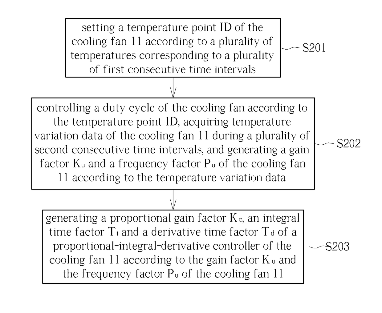
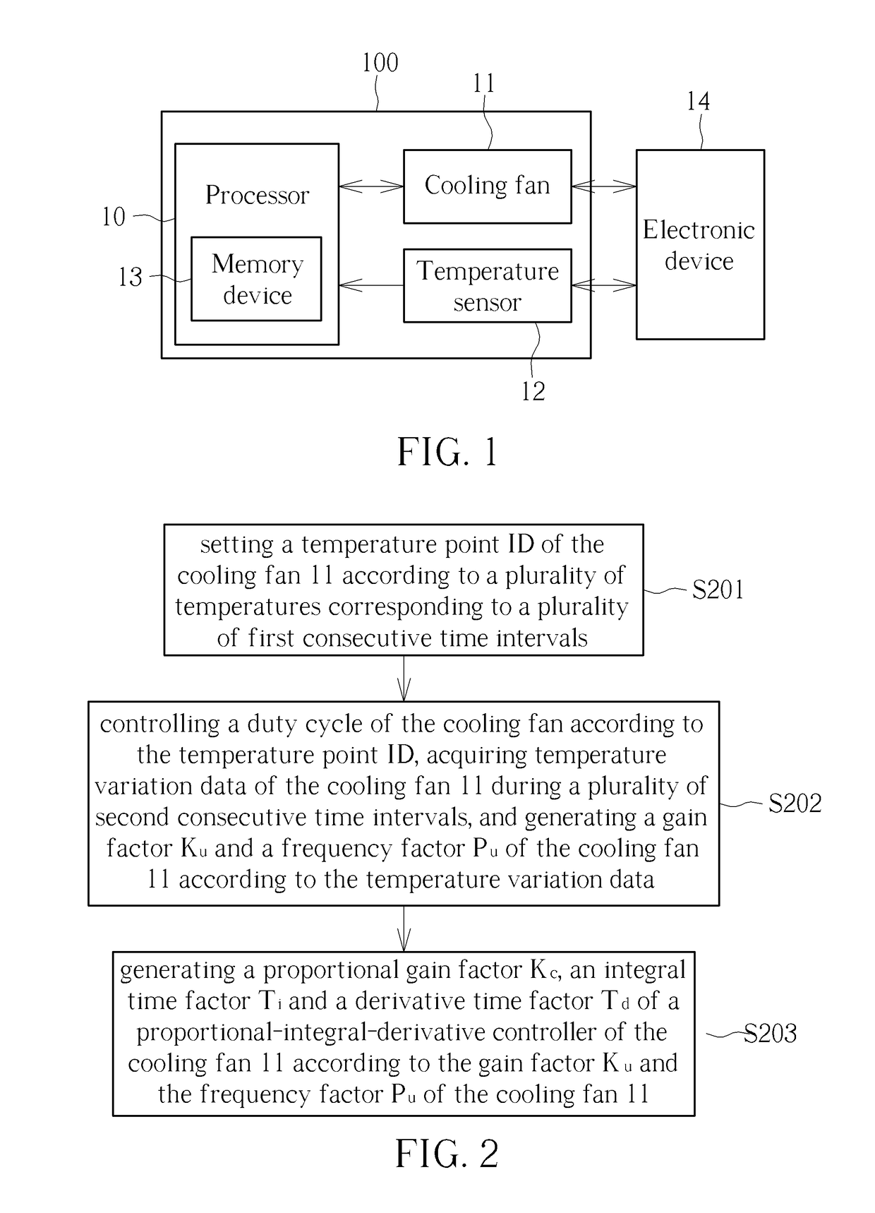
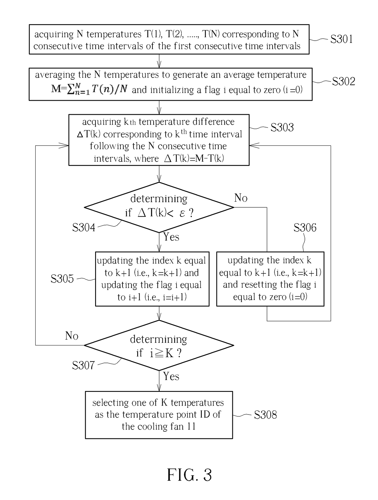
[0014]FIG. 1 is a block diagram of a cooling fan system 100 for optimizing control parameters. In the embodiment, the control parameters are denoted as the proportional-integral-derivative (PID) controller parameters of a cooling fan 11. In other words, the system 100 can test the cooling fan 11 automatically and generate optimal PID parameters, such as a proportional gain factor, an integral time factor, and a derivative time factor. Thus, instead of using a trial and error process-based method for generating PID parameters, the cooling fan system 100 can be regarded as a generator for generating optimal PID parameters. In FIG. 1, the system 100 includes a processor 10, the cooling fan 11 and a temperature sensor 12. The cooling fan 11 can be coupled to an electronic device 14. For example, the cooling fan 11 can be coupled to a central processing unit (CPU), a dual in-line memory module (DIMM), or a graphic card of a server. The temperature sensor 12 is coupled to the electronic d...


PUM


Abstract

After a temperature point of the cooling fan is set according to a plurality of temperatures corresponding to a plurality of first consecutive time intervals, control a duty cycle of the cooling fan according to the temperature point, acquire temperature variation data of the cooling fan during a plurality of second consecutive time intervals, generate a gain factor and a frequency factor of the cooling fan according to the temperature variation data, and generate a proportional gain factor, an integral time factor and a derivative time factor of a proportional-integral-derivative controller of the cooling fan according to the gain factor and the frequency factor of the cooling fan. The plurality of first consecutive time intervals are followed by the plurality of second consecutive time intervals.

Description

BACKGROUND OF THE INVENTION1. Field of the Invention[0001]The present invention illustrates a method for optimizing control parameters of a cooling fan, and more particularly, the method for optimizing proportional-integral-derivative controller (PID) parameters of the cooling fan.2. Description of the Prior Art[0002]With advancement of techniques, various electronic devices are required to achieve high performance and small circuit size. As known, when an electronic device is designed to provide high performance and small circuit size, power consumption and heat generation rate are increased. Thus, a cooling process and a heat dissipation management become two key issues for electronic device design (i.e., such as a personal computer or a server). In general, most electronic devices use a forced convection method to achieve heat dissipation. In the forced convection method, the heat is transferred from a heat source to ambient air. The heat dissipation performance can be improved i...

Claims


Application Information

Patent Timeline
Patent Type & Authority Applications(United States)
IPC IPC(8): G05D23/19
CPCG05D23/1917G05D23/1951F04D27/00F04D27/001F05D2270/20F05D2270/303F05D2270/706G05D23/1919G06F1/206
Inventor LEE, CHENG-MINGTUNG, KAI-YANGLIN, MAO-CHING
Owner INVENTEC PUDONG TECH CORPOARTION
Why Eureka
Try Eureka