Cladding glass for solid-state lasers

a laser and solid-state technology, applied in lasers, laser details, active medium materials, etc., can solve the problem of not being able to enter the doped sapphire, and achieve the effect of high abbe number and well-adjusted

Active Publication Date: 2018-03-29
SCHOTT AG
View PDF7 Cites 7 Cited by
  • Summary
  • Abstract
  • Description
  • Claims
  • Application Information

AI Technical Summary

Benefits of technology

[0018]Sapphire is characterized by a very high Abbe number. The Abbe number of sapphire is about νd=73. This means that the dependency of the refractive indices (ordinary and extraordinary) on the wavelength is relatively low. So that the cladding glass is particularly well adjusted to the sapphire it is advantageous, when also the Abbe number of the cladding glass is very high. Preferably, therefore, the Abbe number of the glasses of the present invention is at least 35, further preferably at least 40, further preferably at least 45, further preferably at least 47, further preferably at least 48. Thus, the Abbe number of the glasses of the present invention is lower than the Abbe number of the sapphire, preferably, by at most 38, further preferably at most 33, further preferably at most 28, further preferably at most 26, further preferably at most 25. So, a satisfactory adjustment of the refractive index of the glass to the refractive index of the sapphire over a comparatively large wavelength range becomes possible. Preferably, the Abbe number of the glasses of the present invention is not higher than 55, further preferably not higher than 52.

Problems solved by technology

There is the risk that the parasitic laser light having entered the cladding glass is reflected at the boundary surface cladding glass / air not facing the core and, after crossing the cladding glass again, again enters the doped sapphire.
Because, when the parasitic laser light is efficiently absorbed in the cladding glass, it is not possible that is enters the doped sapphire again.

Method used


Image

  • Cladding glass for solid-state lasers
  • Cladding glass for solid-state lasers
  • Cladding glass for solid-state lasers

Examples


example glasses

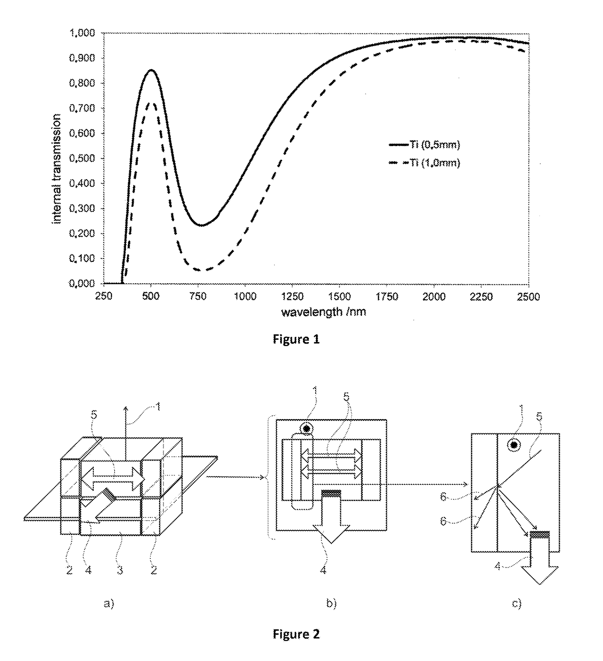
[0124]Different cladding glasses were produced. The example glasses 1 to 3 are lanthanum borosilicate glasses containing CuO. The comparative glasses A to C do not contain CuO. Example glass 3 was cooled with a cooling rate of 5 K per minute. The remaining glasses were cooled with a cooling rate of 40 K per minute.

ExampleExampleExampleComparativeComparativeComparativeglass 1glass 2glass 3example Aexample Bexample CComponent(% by weight)(% by weight)(% by weight)(% by weight)(% by weight)(% by weight)SiO2566555B2O3283030282828BaO0.30.30.30.30.30.3ZnO333333La2O3464950474646ZrO27.77.77.77.77.77.7Nb2O50.60.60.60.60.61.6Y2O3821898CuO111000As2O30.20.20.20.20.20.2Sb2O30.20.20.20.20.20.2Internal0.060.060.060.990.990.99transmis-sion at 800nm for asample witha thicknessof 1 mmRefractive1.76341.75211.75221.76091.76251.7645index at800 nmAbbe48.0648.6148.7749.3949.0648.33number∂n(λ) / ∂λ−0.03639−0.03574−0.03557−0.03559−0.03589−0.03643[nm−1] forλ = 800 [nm]α [−30; 70]×5.865.565.505.895.945.88106 in...


PUM

PropertyMeasurementUnit
wavelengthaaaaaaaaaa
thicknessaaaaaaaaaa
refractive indexaaaaaaaaaa

Abstract

The present invention relates to a glass having a refractive index of at least 1.7 as well as the use of the glass as a cladding glass of a solid-state laser. The invention also relates to a laser component comprising a core of doped sapphire and a cladding glass being placed on said core. The cladding glass is arranged on said core such that light exiting from the core due to parasitic laser activity can enter the cladding glass and can be absorbed there. The present invention also relates to a method for producing the laser component.

Description

CROSS-REFERENCE TO RELATED APPLICATION[0001]The present application claims the benefit of German Patent Application 10 2016 118 364.4, filed on Sep. 28, 2016, which is herein incorporated by reference.BACKGROUND OF THE DISCLOSURE[0002]Optically excited lasers, the amplifying medium of which comprises a crystalline or glass-like solid, which is also called host crystal or host material, are generally referred to as solid-state lasers. The host crystal is doped with ions of an extraneous material. By the introduction of energy into the laser medium electrons are energized to a higher energy level so that excited atoms result. This process is also referred to as pumping. Normally, solid-state lasers are optically pumped. When an atom which has been excited such is stimulated by a photon having the energy to be emitted, then the excited atom again falls back into its normal state and thereby emits a photon with identical energy as well as identical phase position like the stimulating ph...

Claims


Application Information

Patent Timeline
Patent Type & Authority Applications(United States)
IPC IPC(8): H01S3/06H01S3/16C03C3/068
CPCH01S3/0602H01S3/1636H01S3/1625H01S3/1623H01S3/162H01S3/0625C03C3/068H01S3/17C03C4/0071H01S3/0606H01S3/0612H01S2301/02C03C3/064H01S3/06H01S3/16
Inventor CARRE, ANTOINEDANIELOU, ALAINHANSEN, STEFANIEAPITZ, DIRK
Owner SCHOTT AG
Why Eureka
Try Eureka