

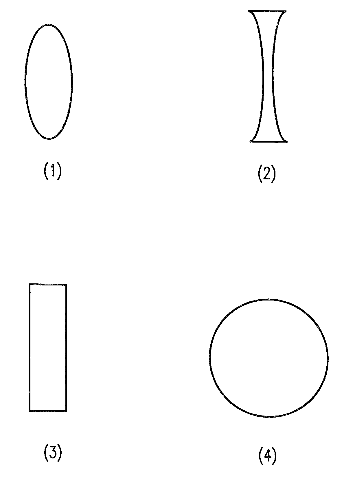
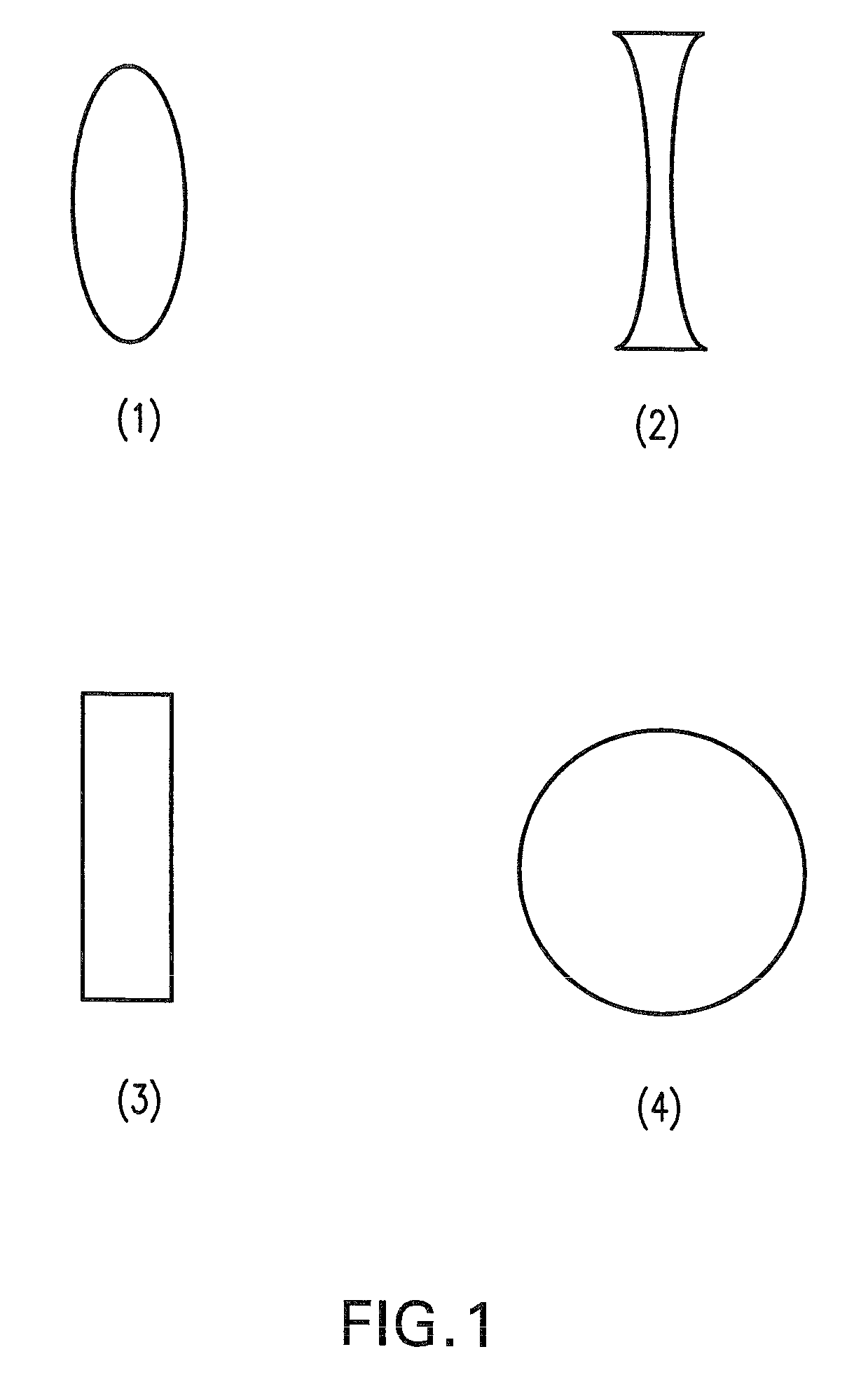
Optical elements made from ceramics comprising one or more oxides of Y, Sc, in and/or lanthanide elements and mapping optics including the optical elements
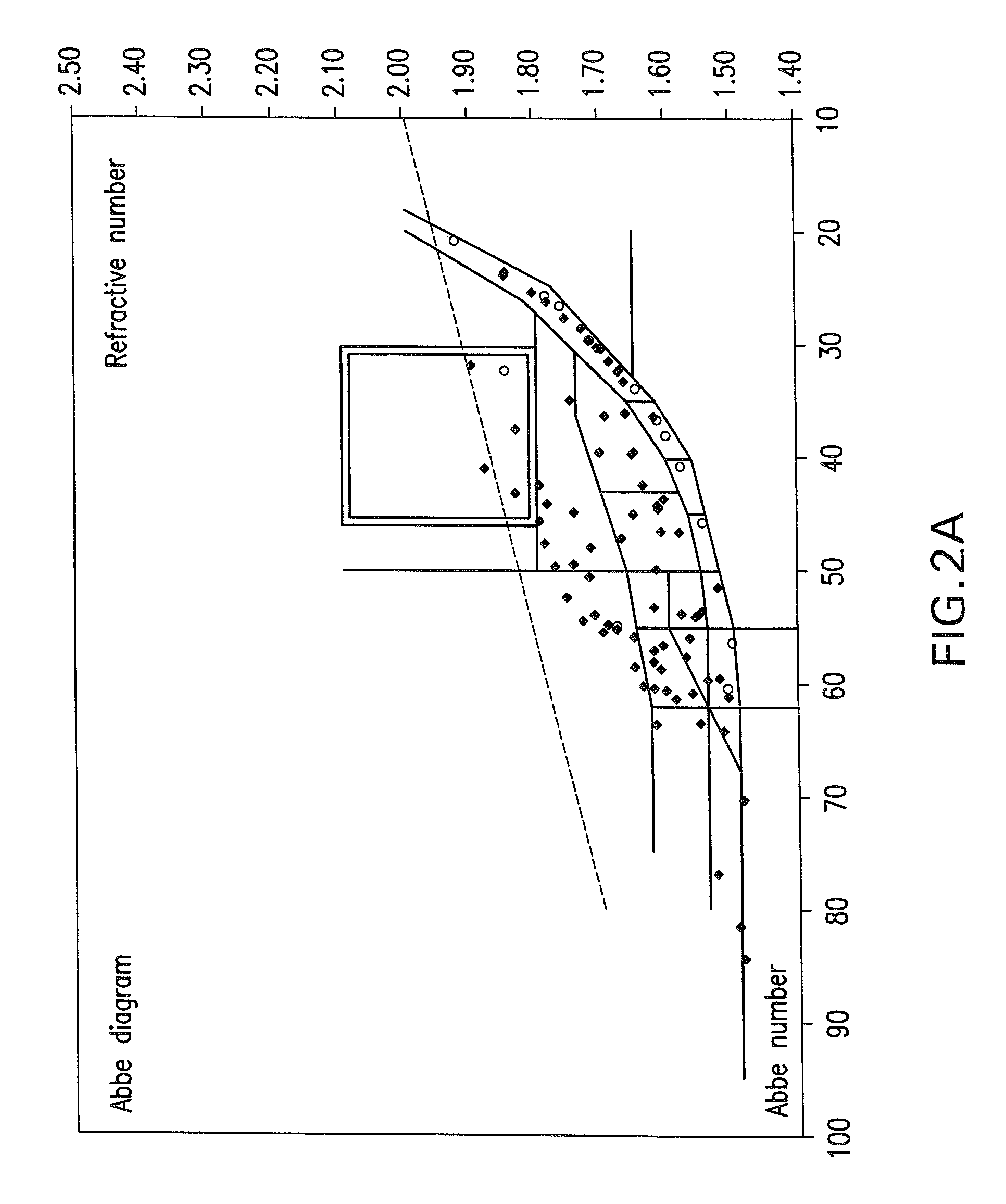
a technology of optical elements and ceramics, applied in the field of refractive, transmissive or diffractive optical elements, can solve the problems of difficult to produce such glasses in large quantities and with sufficient quality, limited development of mapping optics, and enormous limitations in chemical composition, etc., to achieve excellent refractive index, high abbe number, and high abbe number
- Summary
- Abstract
- Description
- Claims
- Application Information
AI Technical Summary
Benefits of technology
Problems solved by technology
Method used
Image

Examples
example
[0110]High purity Y2O3, La2O3 and HfO2 powders were used as starting materials. The powders were mixed with additives and binders and ball milled for 12 h in ethanol. Then the alcohol solvent was removed by drying the milled slurry on a hot plate. The so-obtained powder was pressed with low pressure into required shapes in a metal mold and then cold isostatically pressed at 98 MPa.
[0111]Transparent Y2O3 ceramics were obtained after sintering under vacuum (1×10⁻³ Pa) at 1700° C. for 3 h followed by hot isostatic pressing at 1780° C. for 2 h at a pressure of 196 MPa in Ar atmosphere.
[0112]The Interaction of light with an optically transparent material is given by the addition of reflection, absorption, scattering and specular transmission. The reflection losses are inherent to the material due to Snells' law. The total amount of light emerging from a material is termed “total transmittance”, while its specularly transmitted portion is termed “in-line transmittance” (Tin-line) after ta...
PUM
| Property | Measurement | Unit |
|---|---|---|
| Abbe number | aaaaa | aaaaa |
| Abbe number | aaaaa | aaaaa |
| Abbe number | aaaaa | aaaaa |
Abstract
Description
Claims
Application Information