
Power tool

Active Publication Date: 2018-04-12
MAKITA CORP
View PDF14 Cites 10 Cited by
  • Summary
  • Abstract
  • Description
  • Claims
  • Application Information

AI Technical Summary

Benefits of technology

The present teachings are about how to make a power tool more compact by rationally organizing its structure. The tool also has an illumination apparatus and a manipulation member. The illumination apparatus can turn on before the motor is driven, and the manipulation member can be used to activate the light. This helps protect the illumination apparatus from vibration and makes it easier to confirm the location where work is performed by the tool accessory before starting the actual work.

Problems solved by technology

Consequently, design options for arranging other structural elements within the housing tend to be limited.
Therefore the requirement for cooling is high in such a power tool.

Method used


Image

  • Power tool
  • Power tool
  • Power tool

Examples


first embodiment

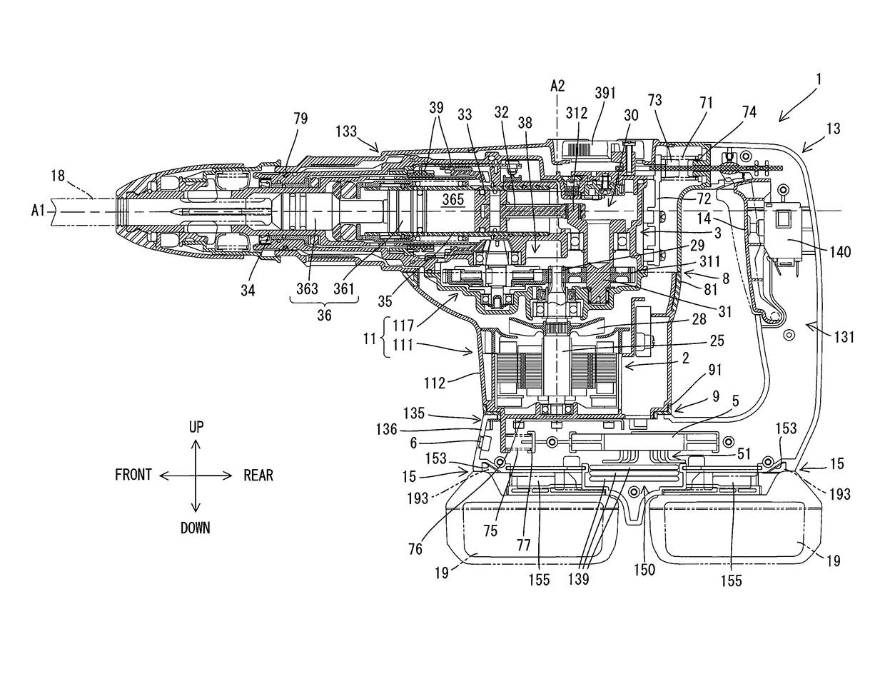
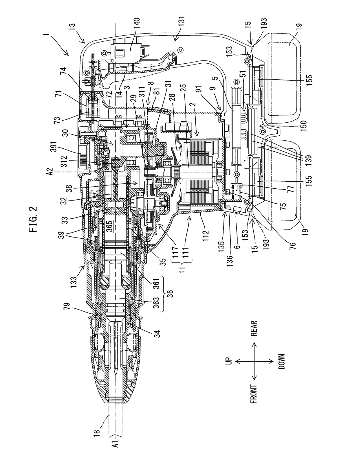
[0029]The hammer drill 1 according to a first embodiment is explained below, with reference to FIG. 1 to FIG. 7. The hammer drill 1 of the present embodiment is configured to perform both an operation (a hammering operation) in which a tool accessory 18, which is mounted on (in) a tool holder 34, is linearly driven (reciprocally driven) along a prescribed impact axis A1 as well as an operation (a drill operation) in which the tool accessory 18 is rotationally driven around the impact axis A1.

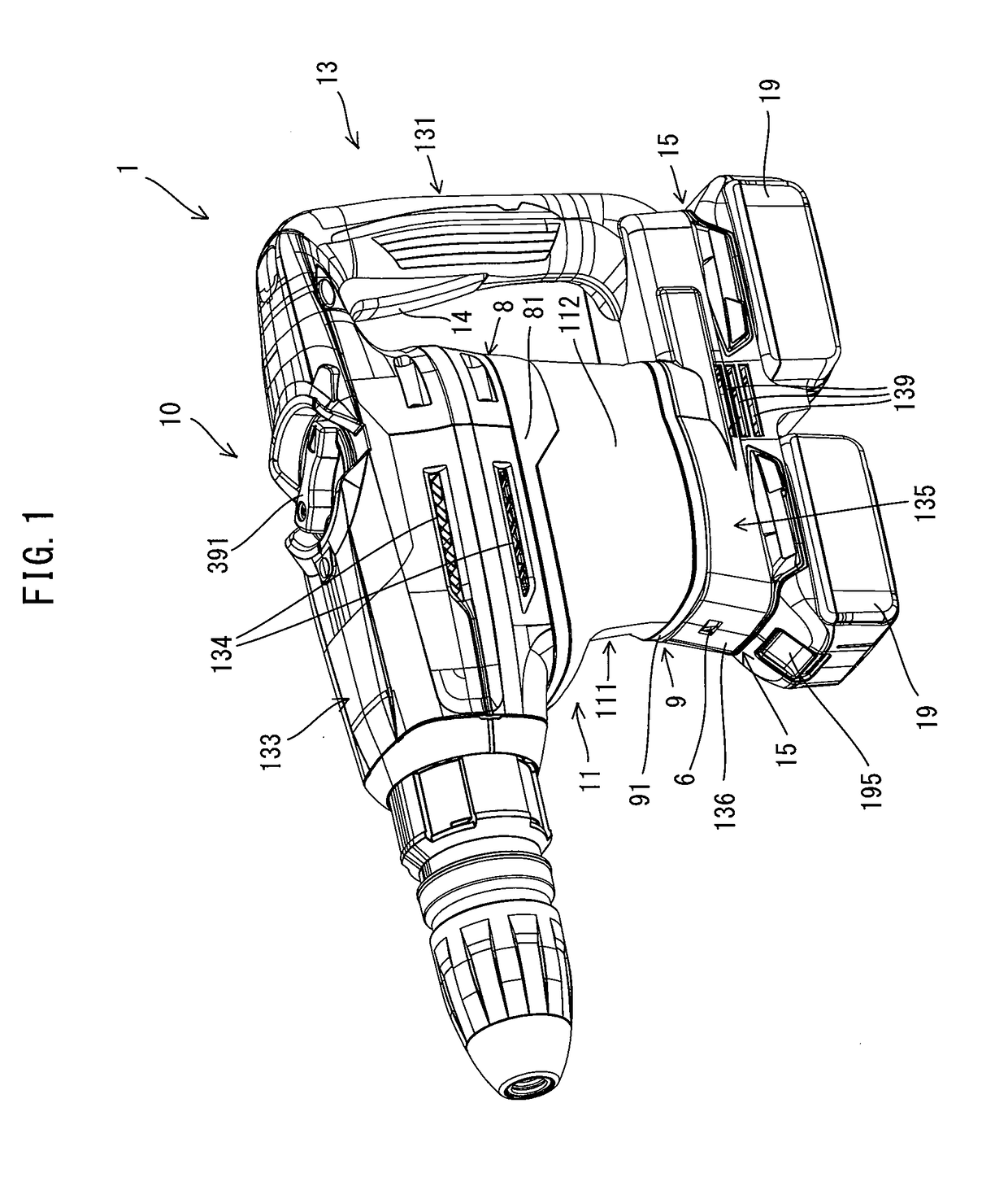
[0030]First, a schematic configuration of the hammer drill 1 will be explained, with reference to FIGS. 1 and 2. The contour (outer periphery) of the hammer drill 1 is formed principally by a housing 10. The housing 10 of the present embodiment is configured as a so-called vibration-isolating housing and comprises a first housing part 11 and a second housing part 13, which is elastically coupled to, and is capable of moving (e.g., sliding in an oscillating manner) relative to, the first housing ...

second embodiment

[0100]A second embodiment will be explained below, with reference to FIG. 8. Most of a hammer drill 101 described by example in the present embodiment has a configuration identical to that of the hammer drill 1 of the first embodiment. Therefore, the illustration and explanation of identical structures are omitted or simplified, and principally only those structures that differ are explained, with reference to the drawings.

[0101]As shown in FIG. 8, as in the first embodiment, a housing 100 of the hammer drill 101 likewise comprises the first housing part 11 and a second housing part 130, which is elastically coupled to, and is capable of relative movement with respect to, the first housing part 11. The configuration and the internal structure of the first housing part 11 are identical to those of the first embodiment. That is, the motor 2 and the drive mechanism 3 are housed in the first housing part 11. More specifically, in the first housing part 11, the drive mechanism 3 is house...


PUM


Abstract

A power tool contains a brushless motor that includes a stator having a stack thickness and an outer diameter, a rotor having a diameter, and a motor shaft extending from the rotor and having a rotational axis. A drive mechanism is operably coupled to the motor shaft and is configured to drive a tool accessory in relation to a drive axis. A first housing houses the motor and the drive mechanism. The drive axis does not intersect the brushless motor, but the rotational axis of the motor shaft intersects the drive axis. The outer diameter of the stator is at least five times greater than the stack thickness. Furthermore, the diameter of the rotor is greater than the stack thickness.

Description

CROSS-REFERENCE TO RELATED APPLICATIONS[0001]The present application claims priority to Japanese patent application serial number 2016-198986 filed on Oct. 7, 2016 and to Japanese patent application serial number 2017-079290 filed on Apr. 12, 2017, the contents of both of which are incorporated fully herein by reference.TECHNICAL FIELD[0002]The present invention generally relates to a portable electrically-driven processing machine, such as, e.g., a power tool that is configured to perform work by driving a tool accessory in relation to a prescribed drive axis.BACKGROUND ART[0003]Some portable (cordless) power tools drive a tool accessory using a rechargeable-type battery (battery pack or battery cartridge) as its motive-power source (power supply). One example of such a power tool is configured to linearly drive (reciprocally drive) a tool accessory in an impact-axis direction using a motor as the drive source. For example, Japanese Laid-open Patent Publication 2016-22567 discloses...

Claims


Application Information

Patent Timeline
IPC IPC(8): B25D16/00B25D17/20B25D17/24F21V33/00
CPCB25D16/006B25D17/20B25D17/24F21V33/00B25D2216/0084B25D2216/0023B25D2222/72B25D2250/121B25D2250/265B25D2250/095B25D2211/068B25D17/043B25D11/00B25D2211/003B25D2216/0015B25D2216/0038
Inventor IIDA, HITOSHIFURUSAWA, MASANORI
Owner MAKITA CORP
Features
  • Generate Ideas
  • Intellectual Property
  • Life Sciences
  • Materials
  • Tech Scout
  • Unparalleled Data Quality
  • Higher Quality Content
  • 60% Fewer Hallucinations
Learn More