Pump unit for a breast pump

a pump and pump body technology, applied in the field of pumping units for breast pumps, can solve the problems of different vacuum levels, system does not take into account the individual anatomy of the woman using the pump, and limits of such systems, and achieves the effect of high reliability over the lifetime of the devi

Active Publication Date: 2018-04-19
KONINKLJIJKE PHILIPS NV
View PDF2 Cites 13 Cited by
  • Summary
  • Abstract
  • Description
  • Claims
  • Application Information

AI Technical Summary

Benefits of technology

[0017]Therefore, it is an object of the present invention to provide a pump unit for a breast pump which substantially alleviates or overcomes the above-mentioned problems. In particular, it is an object of the present invention to provide a pump unit for a breast pump to control a pressure provided by the pump unit accurately with high reliability over device lifetime and in a cost effective manner.

Problems solved by technology

However, there are several limitations of such systems.
The system does not take into account the individual anatomy of the woman using the device.
However, the same pump settings may result in a different vacuum level due to device spread between different breast pumps of the same type.
However, individual testing and calibration of all devices leaving a manufacturing line is time consuming and costly.
However, disadvantages of using an additional pressure sensor attached to a vacuum line are added cost and complexity.
A pressure sensor is an additional part that could potentially fail.
This is particularly an issue in a hospital setting, where breast pumps require a long lifetime and robustness.
Furthermore, the sensor has to be correctly attached to a vacuum line which can make the handling of the breast pump more inconvenient and can have a negative impact on system hygiene due to the additional sensor opening.

Method used


Image

  • Pump unit for a breast pump
  • Pump unit for a breast pump
  • Pump unit for a breast pump

Examples


Embodiment Construction

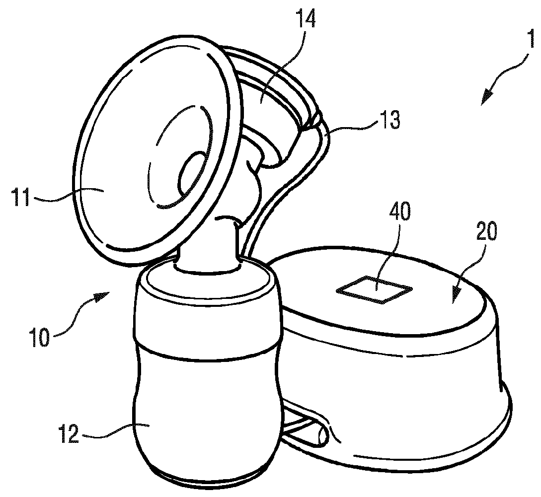
[0061]FIG. 1 shows an embodiment of a breast pump. The breast pump is therein denoted in its entirety with reference numeral 1.

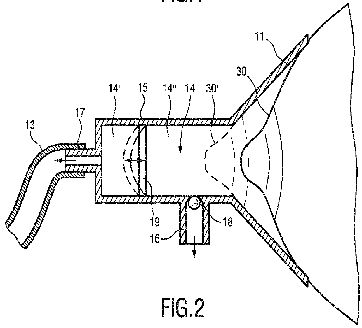
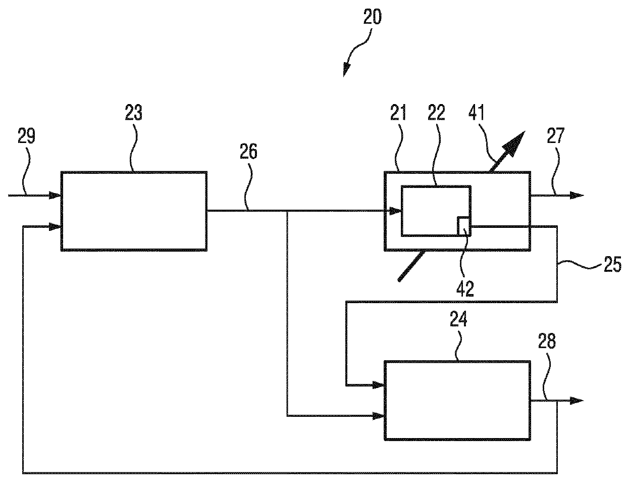
[0062]The breast pump 1 comprises an expression kit 10 and a pump unit 20. The expression kit 10 comprises a breast receiving funnel 11 and a receptacle 12 in form of a baby feeding bottle. The pump unit 20 comprises a vacuum pump 21 with a motor 22 for driving the pump unit and a control unit 23 for providing a control signal for controlling the motor 22 of the vacuum pump 21 (schematically shown in FIG. 3). The vacuum pump 21 of the pump unit 20 is connected to the expression kit 10 via a tube 13. The pump unit 20 may thus be arranged locally remote from the expression kit 10, for example on a desktop or at any other suitable position. However, this is not intended to be limiting. The pump unit 20 comprising the vacuum pump 21 and the control unit 23 could also be arranged at the expression kit 10. The tube 13 is connected to a vacuum chamber 14 that is co...


PUM


Abstract

The present invention relates to a pump unit for a breast pump for extracting milk from a human breast, comprising a motor for driving the pump unit, wherein the motor is configured to provide a motor feedback signal; a control unit for providing a control signal for controlling the motor; and an estimator for estimating a pressure provided by the pump unit based on the motor feedback signal and the control signal; wherein the control unit is configured to adjust the control signal based on the estimated pressure.

Description

FIELD OF THE INVENTION[0001]The present invention relates to a pump unit for a breast pump for extracting milk from a human breast and a corresponding method and computer program.BACKGROUND OF THE INVENTION[0002]Breast pumps are well-known devices for extracting milk from a human breast. A breast pump may be used if a baby is not itself able to extract the milk or if the mother is separated from the baby, for example, if away from the baby at work. The use of a breast pump to extract milk can also be helpful to stimulate lactation in women with low milk supply.[0003]Breast pumps can be manually operated, for example, by squeezing a handle or can also be electrically driven by a small electric motor. An electrically driven breast pump typically comprises one or two expression kits for application to the breast. The expression kits are connected to a pump unit via a tube system. The present invention relates to a breast pump with an electrically driven pump unit.[0004]Breast pumps typ...

Claims


Application Information

Patent Timeline
Patent Type & Authority Applications(United States)
IPC IPC(8): A61M1/06
CPCA61M1/06A61M2205/07A61M2205/10A61M2205/3331A61M2205/3365A61M2205/42A61M2205/50A61M1/06935
Inventor AALDERS, ARNOLDVAN DER LAAN, EWOUT
Owner KONINKLJIJKE PHILIPS NV
Why Eureka
Try Eureka