Scum concentration device

Active Publication Date: 2018-04-19
DALIAN BAY WATER TREATMENT TECH
View PDF0 Cites 2 Cited by
  • Summary
  • Abstract
  • Description
  • Claims
  • Application Information

AI Technical Summary

Benefits of technology

The present invention provides a scum or floating oil concentration device that can effectively collect and discharge high concentration, high viscosity, and low fluidity scum or floating oil. The device can reduce discharge of raw liquid to half of that in prior art. The skimming process using the device minimizes interference during the process and prevents the scum or floating oil from falling into the raw liquid. The device has a narrow upper side and wide lower side structure that reduces the raw liquid content of the scum or floating oil and increases the concentration of the scum or floating oil. A disinfecting device is used to prevent bacterial growth and other related issues during the concentration process. The device has a simple, economical, and practical structure, with a wide scope of applications, suitable for large-scale promotion. The combination of the device and an emulsion scum or floating oil collection device is a continuous treatment system that achieves high efficiency and stability.

Problems solved by technology

However, a large amount of raw liquid constituents are contained in the scum or floating oil or floating oil discharged from these scum or floating oil or floating oil separation devices in current application.
A relatively high percentage of raw liquid content is contained in the scum or floating oil or floating oil, which cannot return to original system for recycling, hence causing a significant waste of raw liquid.
Furthermore, the scum or floating oil containing a large amount of raw liquid increases the workload of the next step.
Besides, the scum or floating oil is easily deteriorated during the process of being gathered and concentrated on the surface of these separation devices, giving out an odor to the surrounding environment, causing pollution.
Moreover, it is very difficult for the existing scum or floating oil separation devices to effectively and promptly remove high-viscosity and high-concentration scum or floating oil to the outside of the separation devices.
The main causes for above defects include: 1) unreasonable design of concentration device; scum or floating oil cannot be concentrated for a long period of time in the device, so as to reduce the liquid content of the scum or floating oil; 2) during the scum or floating oil collection process, a conventional skimming pipe or scum or floating oil scraper relies on scum or floating oil gravity or the scum or floating oil scraper pushes the scum or floating oil to the scum or floating oil receiving mouth; the process when the scum or floating oil moves laterally on the liquid surface interferes with the normal separation, and scum or floating oil movement will cause loss of buoyancy by a part of scum or floating oil, allowing it to fall into the raw liquid, thus negatively affecting the separation.
Thus, the device requires scum or floating oil to have a certain degree of liquidity; for scum or floating oil having a low liquid content, high viscosity and low fluidity, the device will fails to discharge it.
In addition, it is difficult for the device to obtain scum or floating oil with low raw liquid content and high concentration.

Method used


Image

  • Scum concentration device
  • Scum concentration device
  • Scum concentration device

Examples


embodiment 1

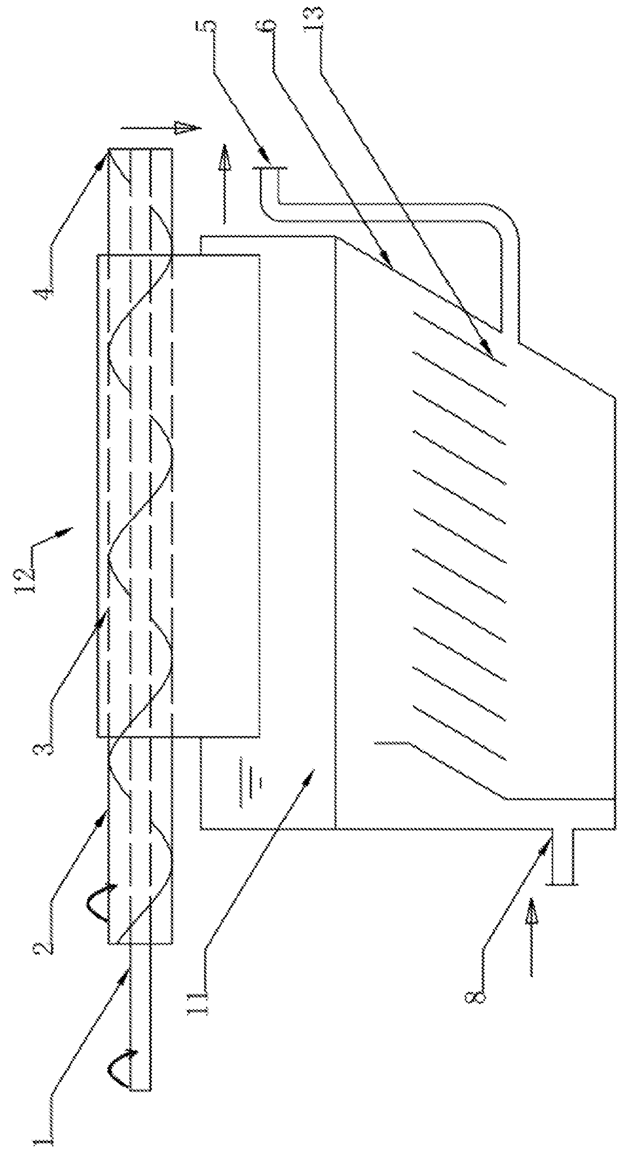
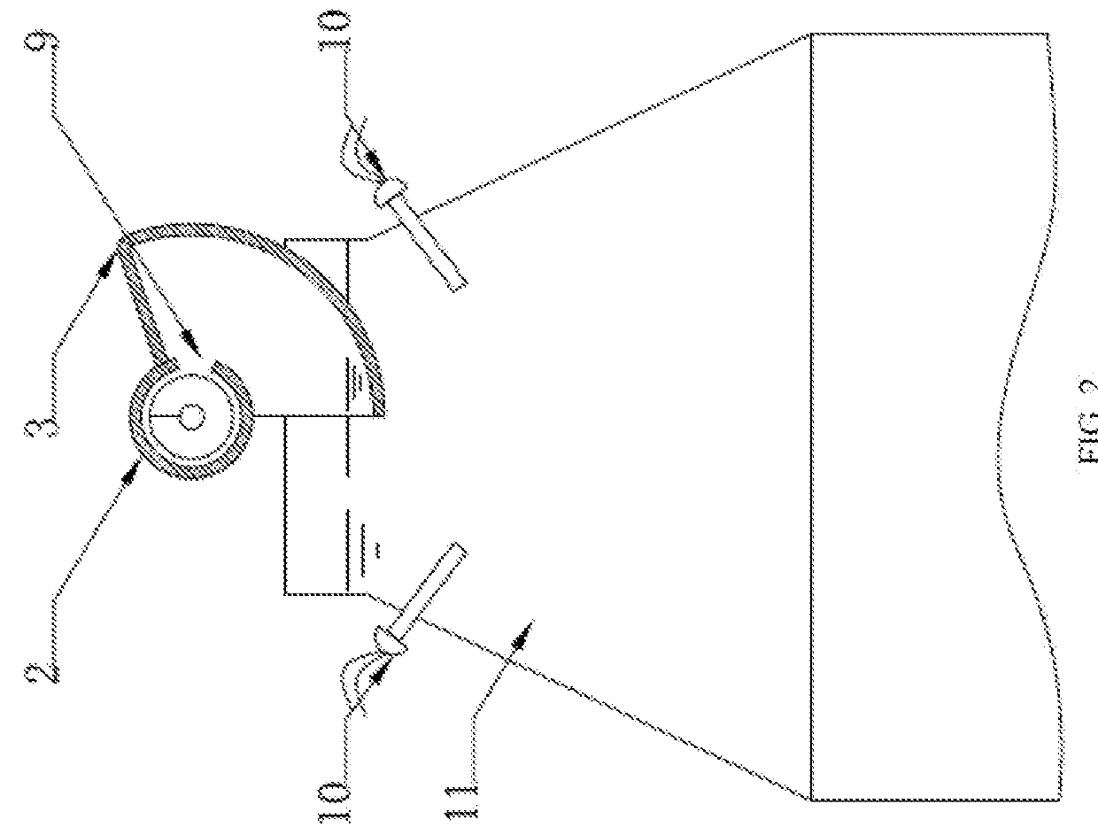
[0025]As shown in FIGS. 1-2, the scum or floating oil concentration device includes a disinfecting device 10, a scum or floating oil concentration cone 11 and a scum or floating oil conveyor 12.

[0026]The following describes the structure of each part.

[0027]The scum or floating oil concentration cone 11 is of a trapezium where the upper side is narrow and the lower side is wide, and the scum or floating oil conveyor12 is arranged above the scum or floating oil concentration cone 11.

[0028]The scum or floating oil conveyor 12 includes a conveying helix 1 rotating around a shaft, a scum or floating oil conveying pipe 2 and a skimmer 3. The conveying helix 1 is arranged inside the scum or floating oil conveying pipe 2. The opening 9 is arranged on the scum or floating oil conveying pipe 2. The fan-shaped skimmer 3 is arranged at the opening 9 on the scum or floating oil conveying pipe 2. The scum or floating oil outlet 4 is arranged on the scum or floating oil conveyor 12. The conveying ...

embodiment 2

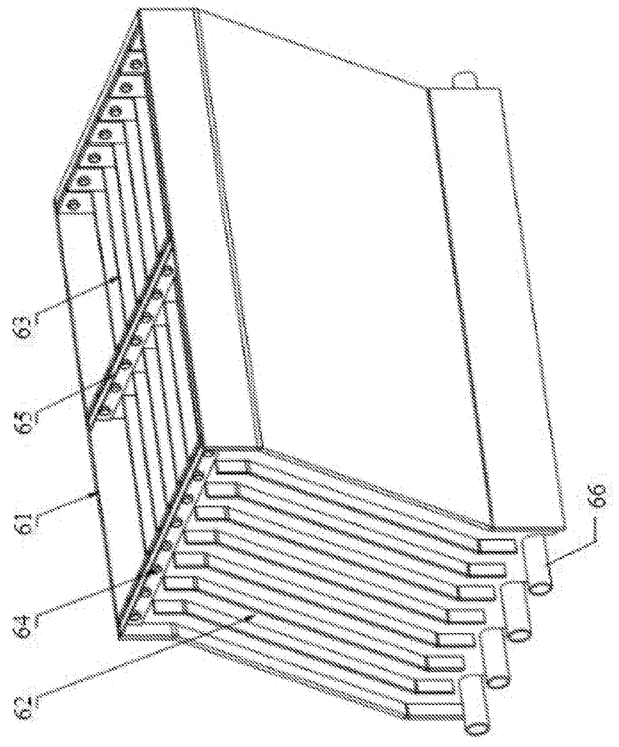
[0032]As shown in FIG. 3, a sloping plate separation assembly with a clamping structure with a uniform liquid-gathering clamping plate is provided in Embodiment 2. Said sloping plate assembly may replace the inclined separation plate 13 in Embodiment 1, installed in the separation device 6. Said sloping plate assembly includes a supporting plate 61, a multi-opening clamping plate 62, a sloping plate 63, a fastening plate 65 and a collector pipe 66. Both sides of the multi-opening clamping plate 62 are fixed on the supporting plate 61. The angle between the multi-opening clamping plate 62 and the perpendicular direction is 30°. The multi-opening clamping plates 62 are installed in parallel. More than one multi-opening clamping plate 62 may be arranged in parallel according to the strength of the sloping plate. Parallel sloping plate grooves are defined on the multi-opening clamping plate 62. The sloping plate 63 is fixed on the multi-opening clamping plate 62 by the sloping plate gro...

embodiment 3

[0033]As shown in FIGS. 4-5, a scum or floating oil collection and concentration system is provided in Embodiment 3. The scum or floating oil collection and concentration system comprises a scum or floating oil concentration device comprising a scum or floating oil concentration cone 11 and a scum or floating oil conveyor 12 fixed on said scum or floating oil concentration cone 11, and an emulsion scum or floating oil collection device comprising a emulsion device 14 and a floating weir skimmer 15.

[0034]The scum or floating oil concentration cone 11 is of a trapezium where the upper side is narrow and the lower side is wide. Said scum or floating oil conveyor 12 includes a conveying helix 1 rotating around a shaft, a scum or floating oil conveying pipe 2 and a skimmer 3. Said conveying helix 1 is arranged inside said scum or floating oil conveying pipe 2. An opening 9 is arranged on said scum or floating oil conveying pipe 2. Said fan-shaped skimmer 3 is arranged at said opening 9 o...


PUM

PropertyMeasurementUnit
Concentrationaaaaaaaaaa

Abstract

A scum or floating oil concentration device comprises a scum or floating oil concentration cone (11) and a scum or floating oil conveyor (12). Said scum or floating oil conveyor (12) is arranged above said scum or floating oil concentration cone (11). Said scum or floating oil conveyor (12) comprises a conveying helix (1) rotating around a shaft, a scum or floating oil conveying pipe (2) and a skimmer (3). Said conveying helix (1) is arranged inside said scum or floating oil conveying pipe (2). An opening is arranged on said scum or floating oil conveying pipe (2). Said skimmer (3) is arranged at said opening of said scum or floating oil conveying pipe (2). An inclined separation plate (13) and a scum or floating oil collection and concentration system are further provided in the present invention.

Description

CROSS-REFERENCE TO RELATED APPLICATIONS[0001]This application is a continuation of International Patent Application No. PCT / CN2016 / 074534 with a filing date of Feb. 25, 2016, designating the United States, now pending. The content of the aforementioned application, including any intervening amendments thereto, are incorporated herein by reference.TECHNICAL FIELD[0002]The present invention relates to a scum or floating oil treatment device, in particular to a scum or floating oil or tramp oil concentration device.BACKGROUND OF THE PRESENT INVENTION[0003]Scum or floating oil or floating oil separation device has been widely used in liquid separation industry, such as grease trap, oil water separator, etc. The scum or floating oil or floating oil separated by these devices will be discharged through a skimming pipe or by a scum or floating oil scraper. However, a large amount of raw liquid constituents are contained in the scum or floating oil or floating oil discharged from these scum...

Claims


Application Information

Patent Timeline
IPC IPC(8): B01D21/02B01D21/24
CPCB01D21/02B01D21/24B01D17/0211B01D17/0214B01D17/045B01D21/0045B01D21/2433B01D21/2438
Inventor XU, YIN
Owner DALIAN BAY WATER TREATMENT TECH
Why Eureka
Try Eureka