Method for robust and noise-tolerant SpO2 determination

Inactive Publication Date: 2020-02-27
SANDBEKKHAUG ODD INGE +2
0 Cites 4 Cited by

AI-Extracted Technical Summary

Problems solved by technology

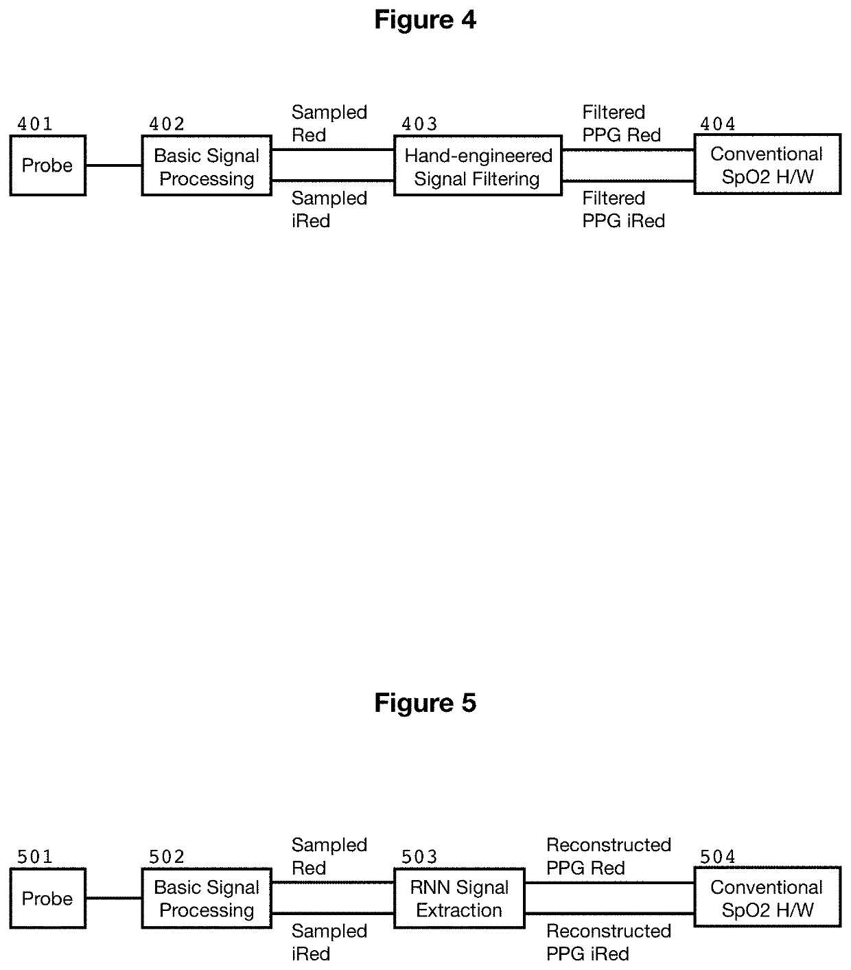
In order to combat noise, approaches have been developed to maintain the measurement probe in a fixed position relative to the patient body, thereby limiting the possibility of noise artifacts due to movement.
These inventions somewhat improve the reliability of signal acquisition but do not effectively address noise.
These inventions implement variou...

Method used

[0069]The RNN signal reconstruction model can alternatively be included within the SpO2 sensor device by instantiating the RNN model in an FPGA...

Benefits of technology

[0049]The key advantage of the invention is that SpO2 devices deliver accurate results in presence of noise, and can therefore be used in a wider range of applications.
[0050]The invention can reduce the number of corner-cases which are not covered by traditional signal processing methods. At low perfusion levels, motion artifacts and noise are more prevalent and reduces the effective signal-too-noise ratio. By using our RNN approach, higher levels of noise and interference may be tolerated.
[0051]The traditional methods of hand-engineering (fixed) signal processing algorithms are prone to poor performance in corner-cases. Noise generation is a simpler t...

Abstract

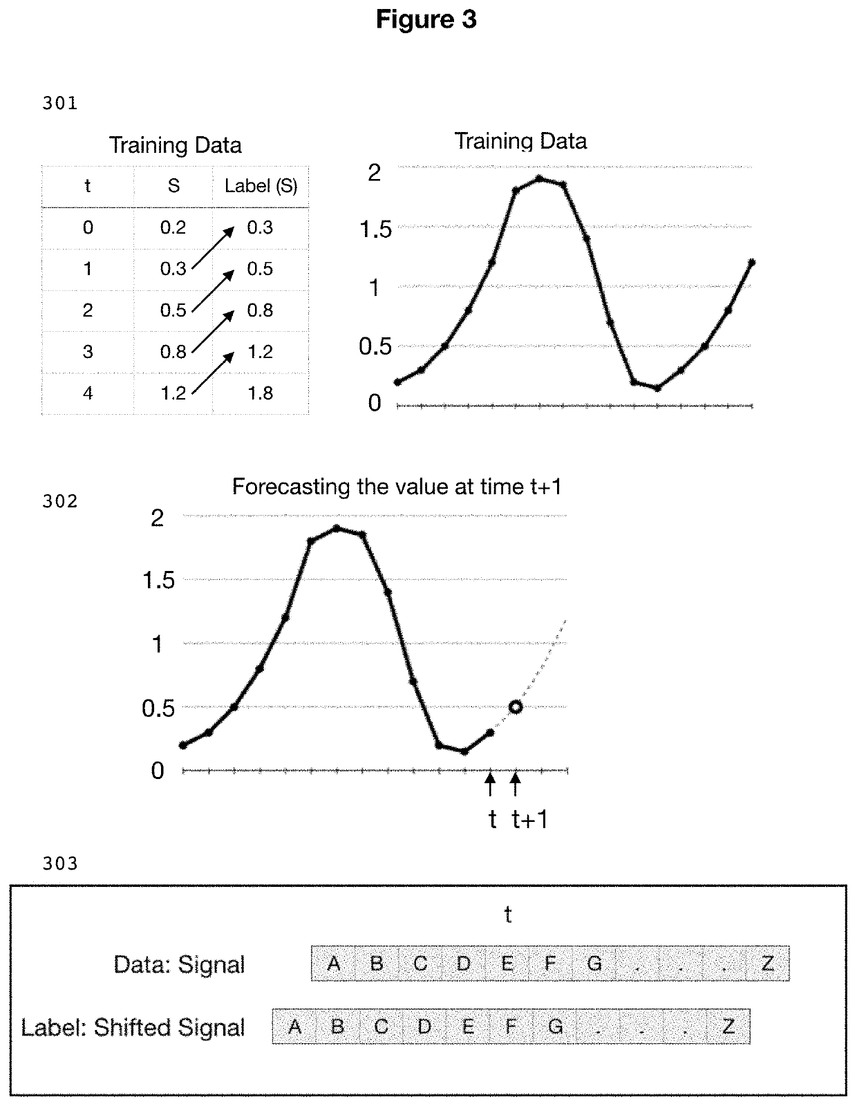
A recurrent neural network model is trained to ignore noise components and accurately reconstruct quasi-periodic SpO2 signal waveforms. In accordance with the invention, the neural network is trained on a carefully structured data set so as to be able to (1) be able to use deep learning techniques for model training, and (2) utilize traditional time-series forecasting neural network techniques to produce a clean reconstructed signal from potentially noisy inputs. A novel technique is used to construct a training data set that turns a forward-looking RNN forecasting model into a “sideways-looking” model which acts as a sophisticated noise filter.

Application Domain

Technology Topic

Image

  • Method for robust and noise-tolerant SpO2 determination
  • Method for robust and noise-tolerant SpO2 determination
  • Method for robust and noise-tolerant SpO2 determination

Examples

  • Experimental program(1)

Example

[0066]There are several preferred embodiments possible: embodiment as part of an SpO2 sensor device, embodiment as an appendage to a sensor device (such as laptop/monitor or smartphone) and embodiment completely separate from the SpO2 sensor device (such as a hosted cloud service).
Embodiment as Part of the SpO2 Sensor Device
[0067]The RNN signal reconstruction model can be included within the SpO2 sensor device [701] itself by instantiating the RNN model in a simple firmware/software environment within a low-cost embedded CPU. Many SpO2 devices already implement signal processing on-device and adding the RNN processing step is feasible on such a platform.
[0068]The sensor output [702] is routed to the CPU [703] and fed to the RNN software model [704]. The reconstructed signal [705] is routed from the output of the RNN model to the parameter processing and display portion [706] of the SpO2 device.
[0069]The RNN signal reconstruction model can alternatively be included within the SpO2 sensor device by instantiating the RNN model in an FPGA [702] or ASIC [702] instead of, or in addition to, the embedded CPU. This can improve real-time performance and lower the total solution cost.
Embodiment as an Appendage to the SpO2 Sensor Device
[0070]The output from the basic SpO2 sensor device [801] can be connected to an external computing device [802], on which the RNN model [803] runs and processes the SpO2 input signal [804]. The reconstructed signal is routed to final parameter processing and display [805]. The term “external computing device” here refers to, but is not limited to, embedding in patient monitor equipment, laptops, mobile phones, tablets and any other device capable of basic computing.
Embodiment Completely Separate from the SpO2 Sensor Device
[0071]The RNN signal reconstruction can execute completely separately in time and space from the SpO2 sensor device in an external computing environment [901] such as a cloud server. An SpO2 signal reconstruction can be configured to process SpO2 samples either as a complete datafile [902] (this would be a post-processing application), or on streaming data [903] in near-realtime. The resulting reconstructed signal can then either be prepared for further immediate processing and display, or stored in a data file for later retrieval.
Terminology
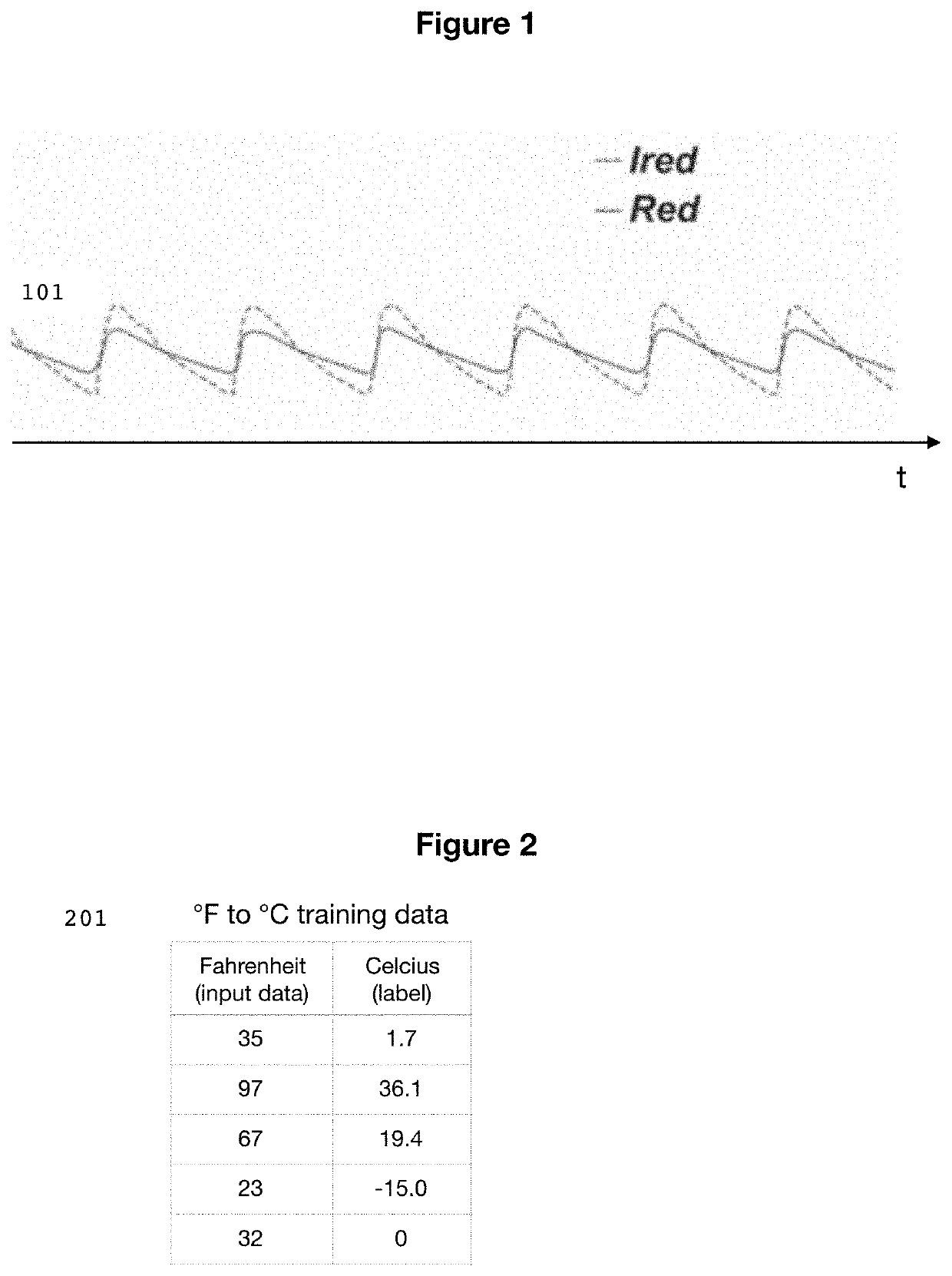
[0072] 1. Photoplethysmography (PPG): a simple and low-cost optical technique that can be used to detect blood volume changes in the microvascular bed of tissue [0073] 2. Noisy data: data samples (and sequences of data samples) which consist of a mix of true physiological signal and noise components [0074] 3. Tethered computing environment: computing environment connected in near proximity to the sensor device either via physical cabling, or via wireless connectivity such as Bluetooth or WiFi. [0075] 4. Un-tethered computing environment: computing environment which is able to process signal waveforms, but which is not connected in near physical proximity of the sensor device, such as a remote server or cloud computing environment. These computing environments are sometimes referred to “off-line” computing or “batch computing” environments. [0076] 5. Waveform extraction: applying the RNN model to a noisy data signal waveform and returning a reconstruction of the original true signal waveform [0077] 6. Synthesized samples: artificially generated signal data [0078] 7. Organic samples: signal data recorded from a real-life sensor [0079] 8. Characteristic waveform: the general morphology of a signal waveform for a given type of physiological signal, including but not limited to SpO2 waveforms, ECG/EKG cardiac waveforms etc. The characteristic waveform can be quasi-periodic in nature, for example such as that of EKG generated by heartbeats. [0080] 9. Morphology: shape, in our case the general shape of a waveform when plotted as values (y) over time (x). [0081] 10. Quasi-periodic: a signal that is periodic in nature, but not exactly identical from period to period. Quasi-periodic signals have a recognizable waveform shape but may exhibit variance within that shape over time and between measurement subjects. [0082] 11. Recurrent Neural Networks (RNN): a type of neural networks which are able to recognize and construct order-dependent sequences of values. [0083] 12. Deep Learning: A class of Neural Network architectures which rely on multiple layers of neurons to learn complex and non-linear functions expressed as relationships between input data (features) and output results (labels). [0084] 13. End-to-End Deep Learning: A Deep Learning technique which bypasses the manual feature engineering phase and achieves improved neural network performance by adding more network layers and a (much) larger training set.

PUM

no PUM

Description & Claims & Application Information

We can also present the details of the Description, Claims and Application information to help users get a comprehensive understanding of the technical details of the patent, such as background art, summary of invention, brief description of drawings, description of embodiments, and other original content. On the other hand, users can also determine the specific scope of protection of the technology through the list of claims; as well as understand the changes in the life cycle of the technology with the presentation of the patent timeline. Login to view more.

Similar technology patents

Capacitive level measurement and detection device

InactiveUS20060285212A1Accurate resultMirrorsResistance/reactance/impedenceLevel measurementSynchronous rectifier
Owner:IMF ELECTRONIC GMBH

System and method for updating biometric evaluation systems

PendingUS20210319085A1Accurate resultMetadata audio data retrievalDatabase updatingEngineeringAlgorithm
Owner:NICE LTD

Classification and recommendation of technical efficacy words

  • Reduce number
  • Accurate result

GCN-based text classification method

ActiveCN111274405ASolve the sparsity problemAccurate resultNatural language data processingNeural architecturesClassification resultTest set
Owner:BEIJING UNIV OF TECH
Why Eureka
Try Eureka